Yamaha YXZ1000R Valve Clearance Adjustment
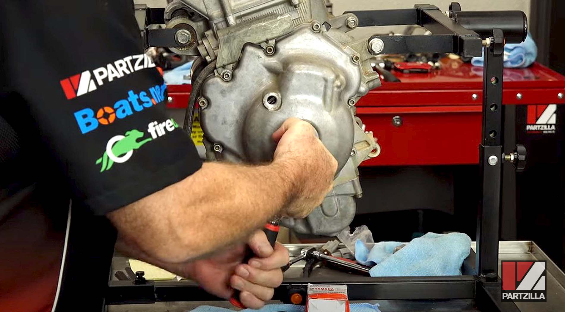
Welcome to the valve adjustment section of our 2016 Yamaha YXZ1000R engine rebuild, in which we measure and set the valve clearance after having installed the head.
Besides adjusting the valves, we're swapping out the OEM automatic chain tensioner with an aftermarket manual unit. Watch the video above or read on below to learn how we set the valve clearance for our Yamaha YXZ1000R engine rebuild project.
See the parts diagrams:
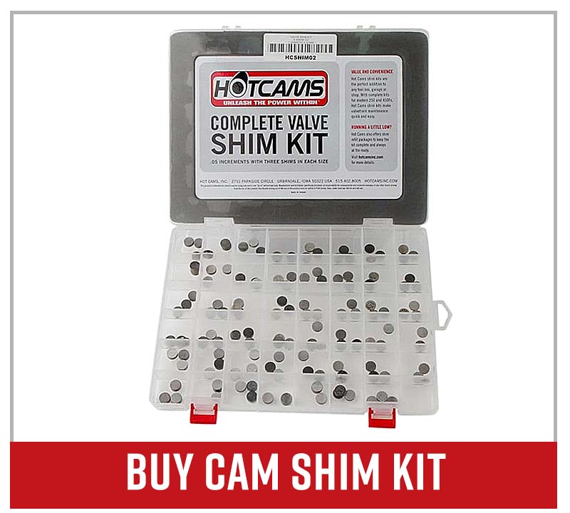
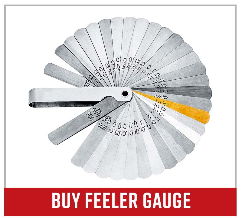
Tools and Parts -Yamaha YXZ1000R Valve Adjustment
- Ratchet and extensions
- Digital torque wrench
- Zip ties
- Feeler gauge
- Valve lifter
- Assembly lube
In the previous video for this engine rebuild, in which we installed the head, we left the engine off on the split overlap on cylinder 3.
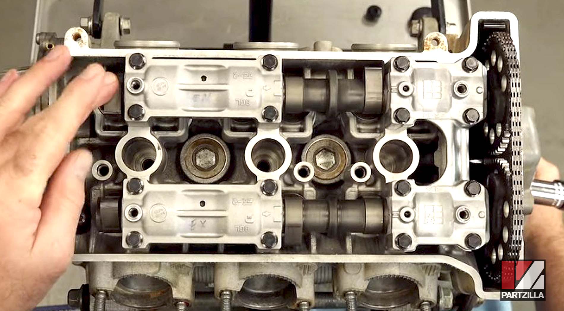
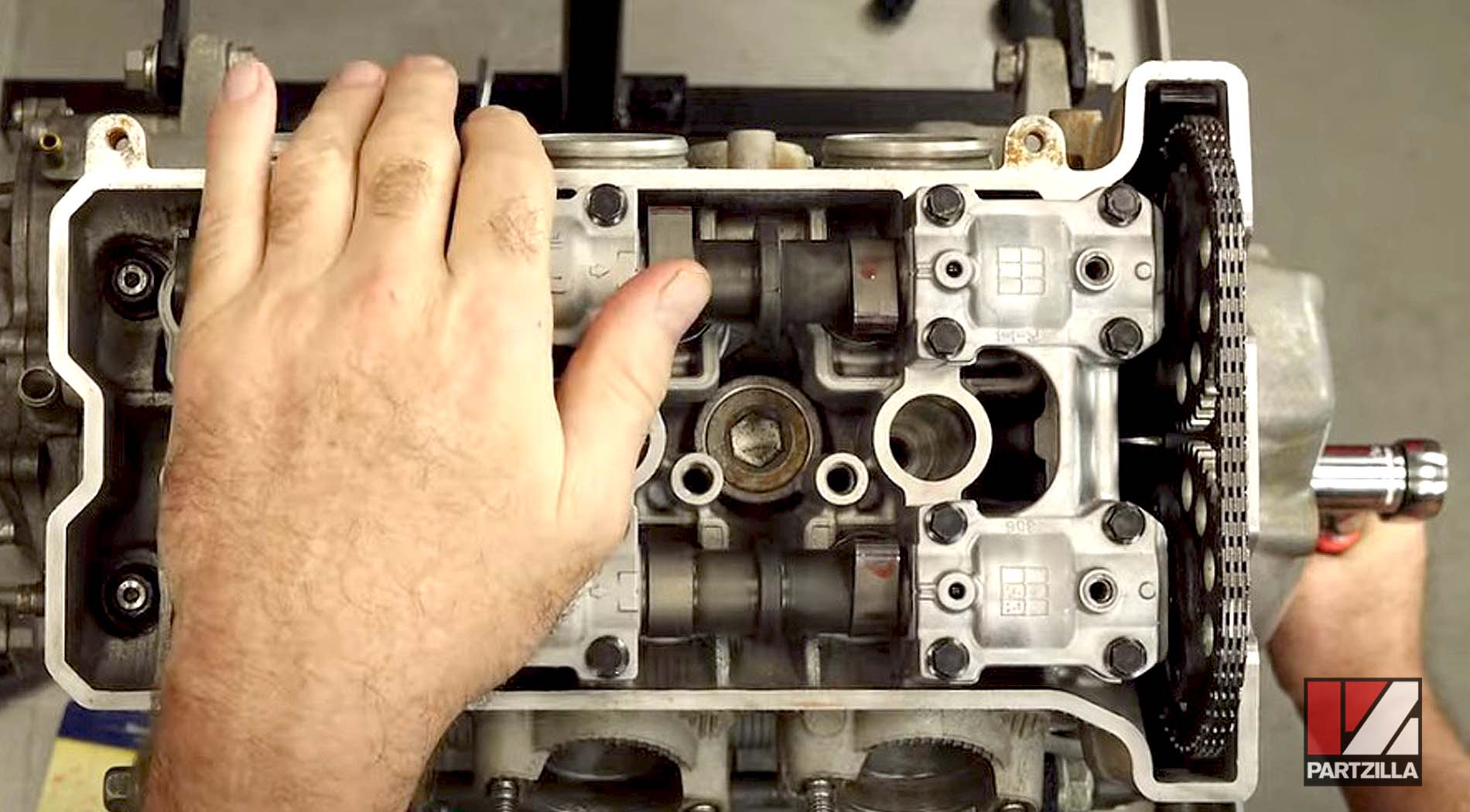
To do the first measurement, we bring it around 360 at the crank so it’s at the compression stroke. When we do this, our cams (which are pointed down on split overlap) will point up (compression stroke) so we can take our measurements.
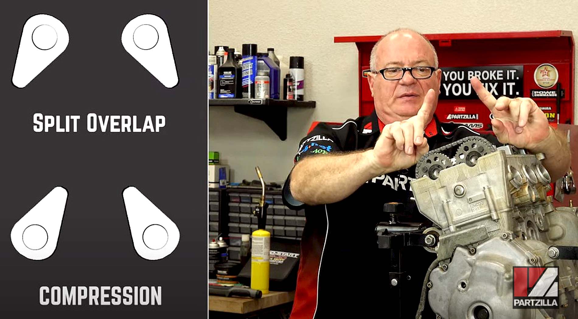
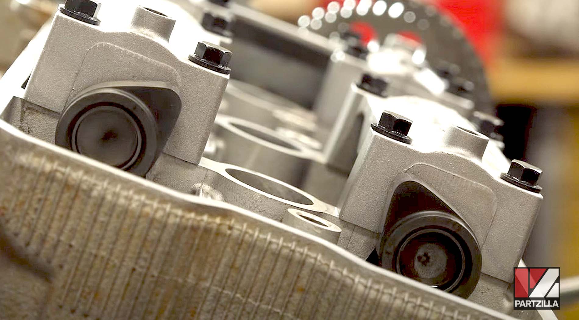
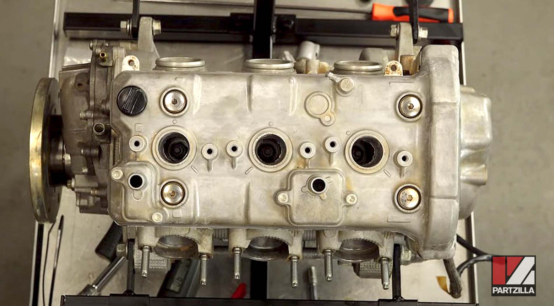
We bring the engine to top dead center, using the timing mark as our guide and making sure the cam lobes are pointing up so we can go in there and check clearances.
NOTE: When setting TDC, if you miss the mark, don’t turn it backward, because you could make it jump time.
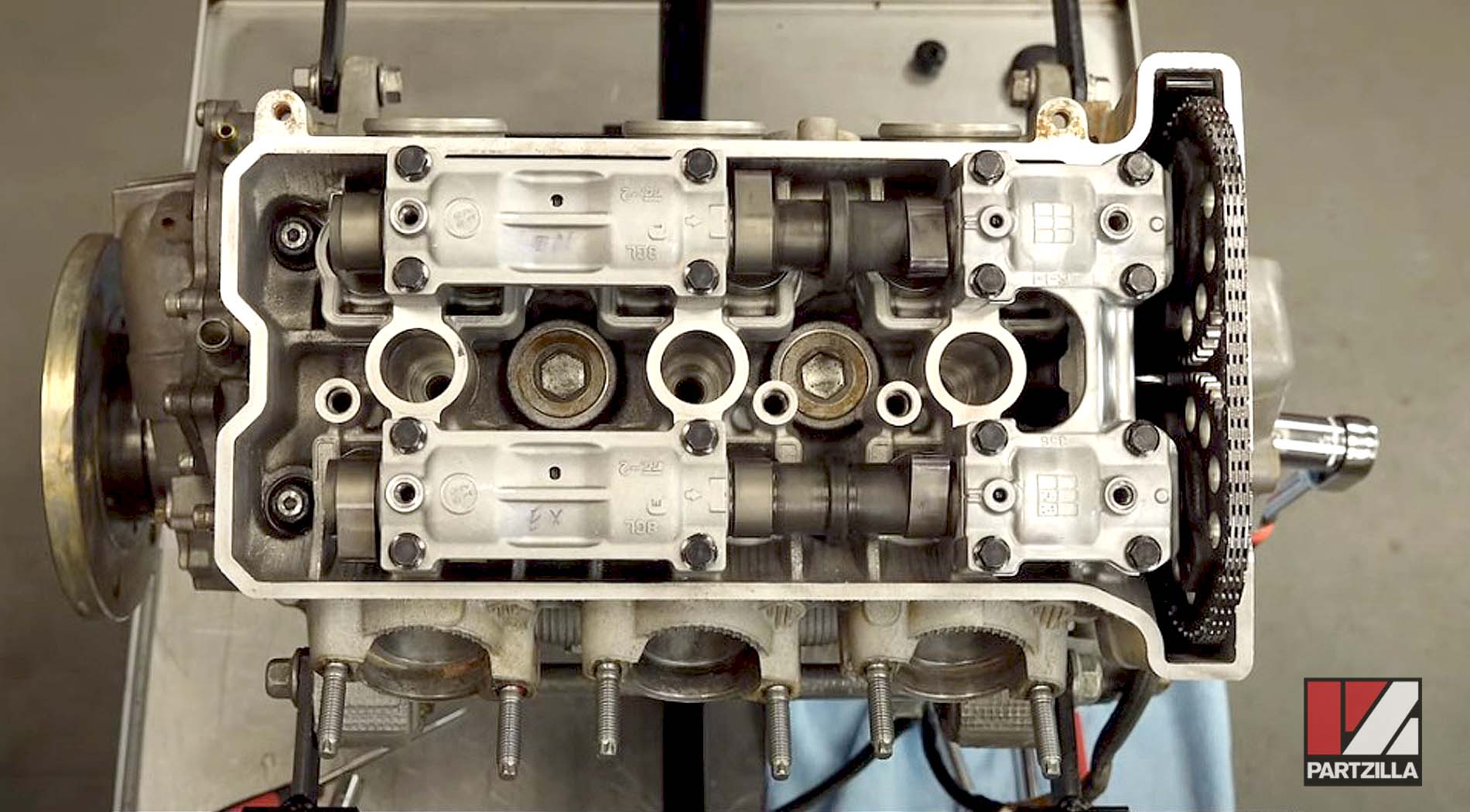
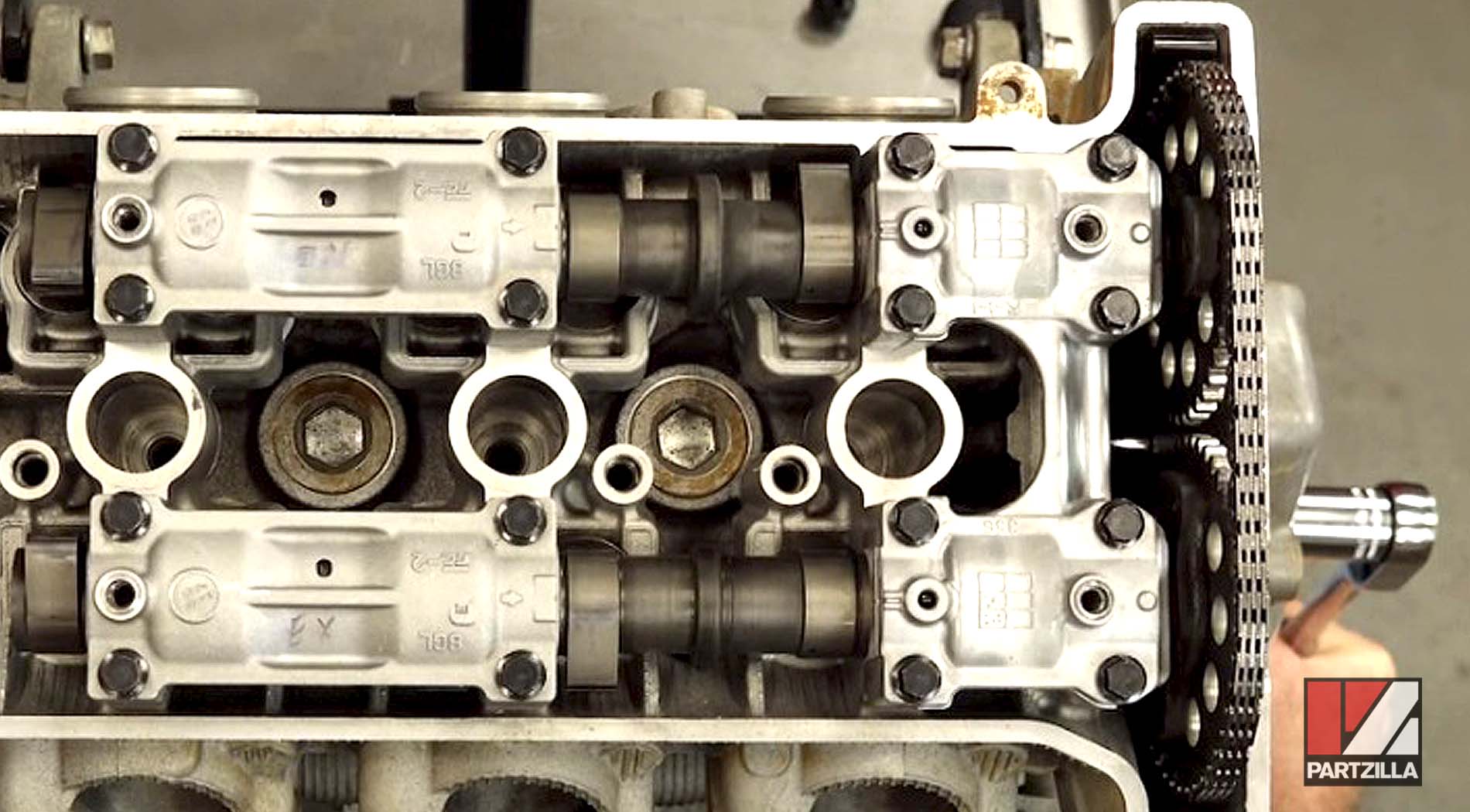
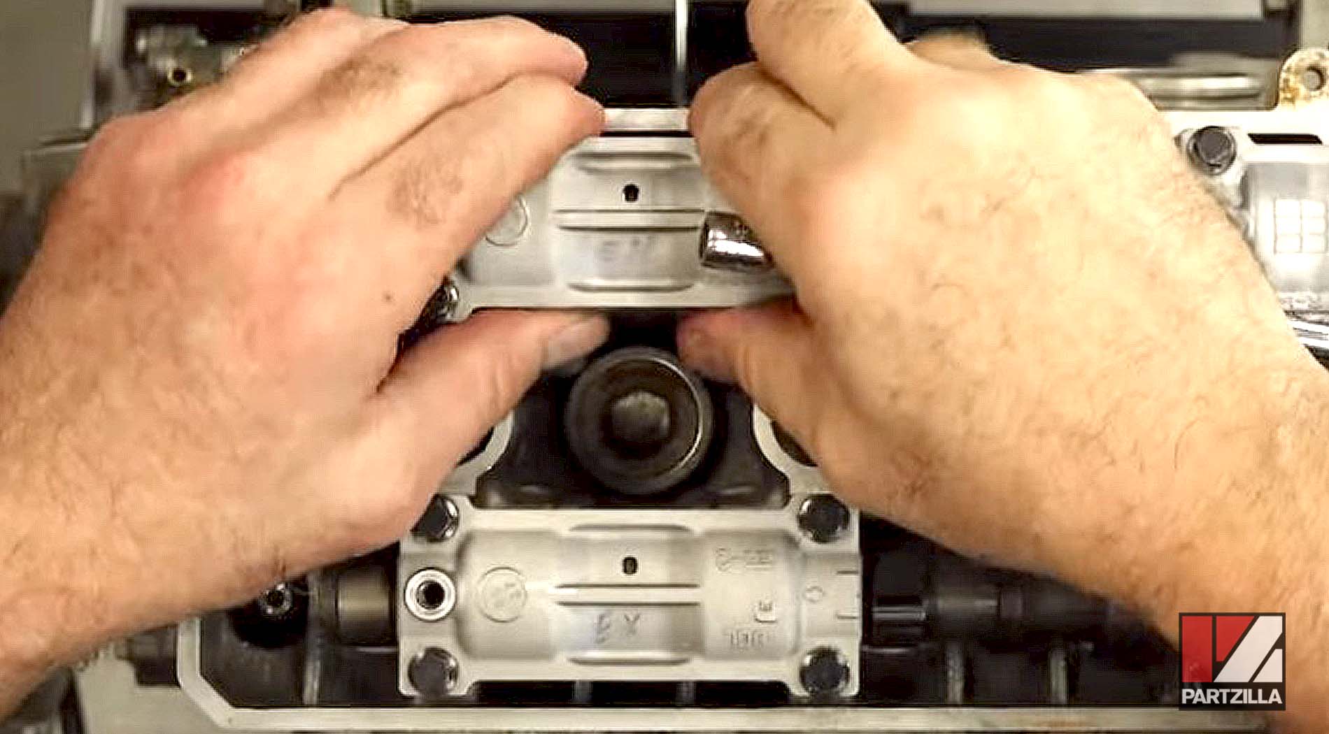
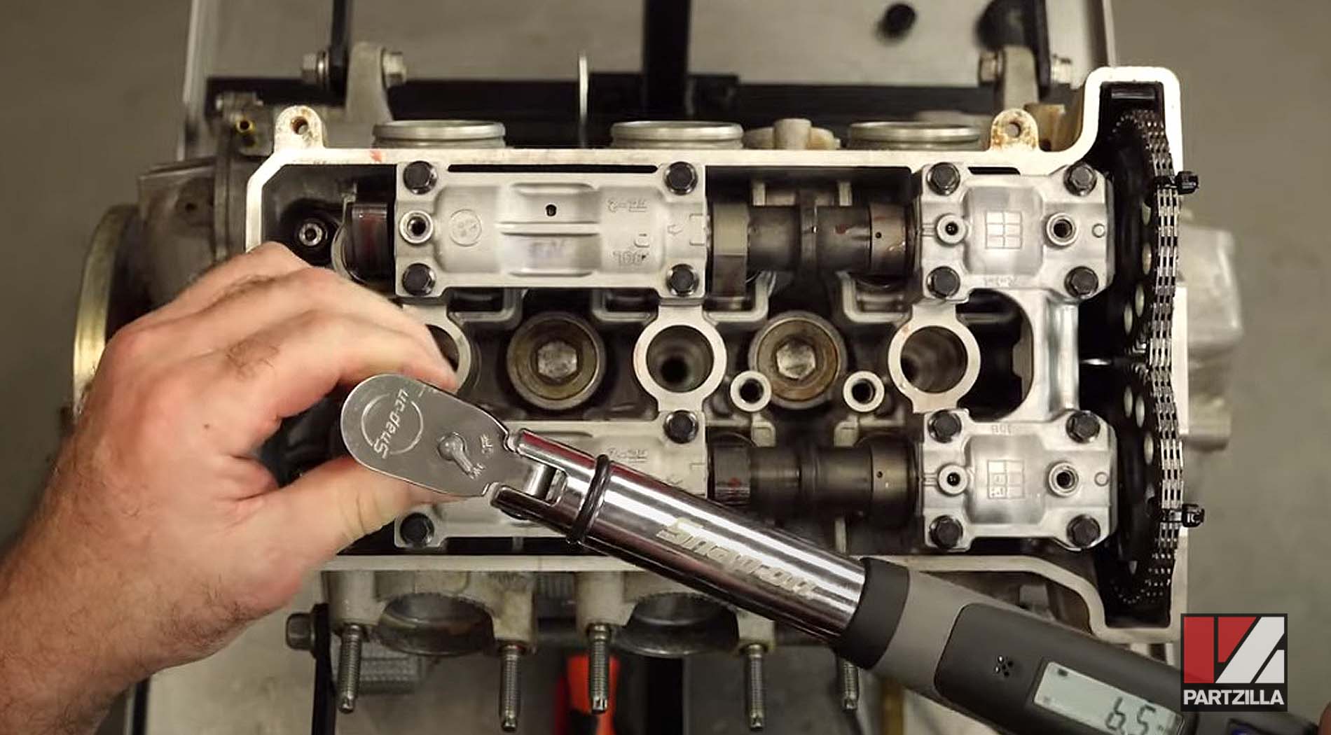
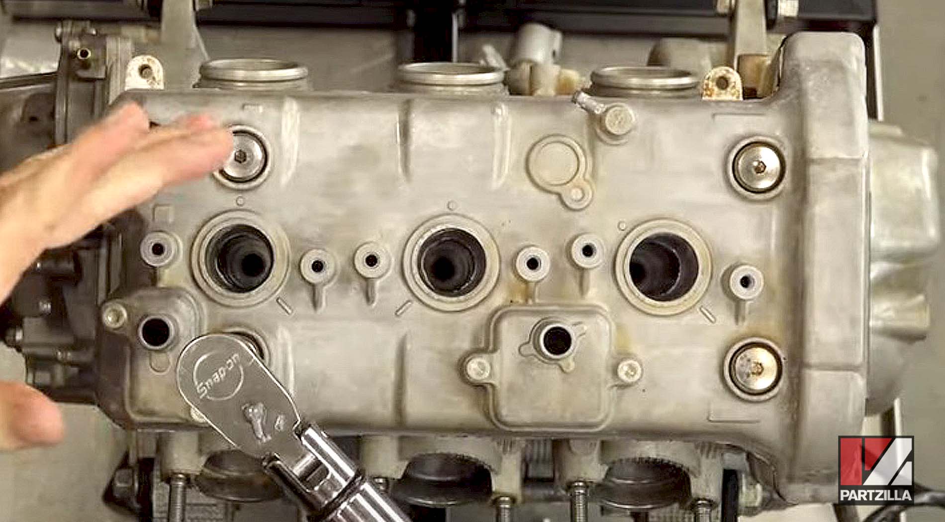
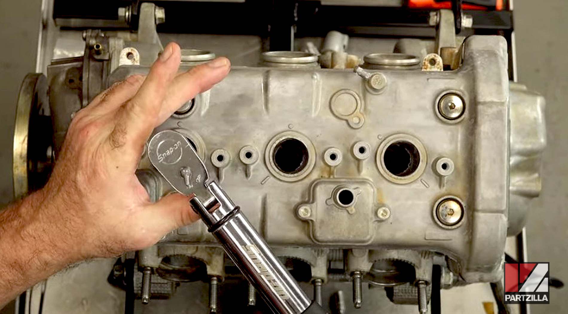
Next, we torque the cam caps to 7.2 foot-pounds, going across the board working from inside out.
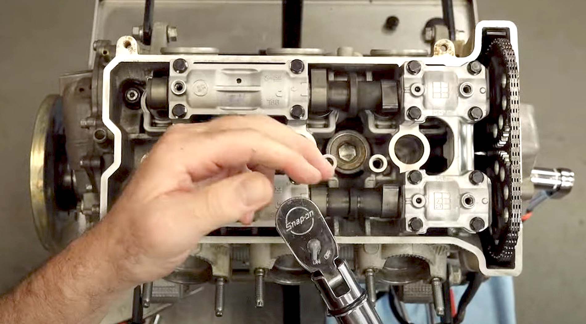
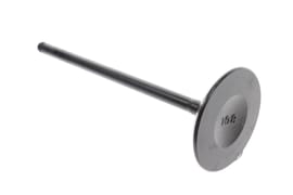
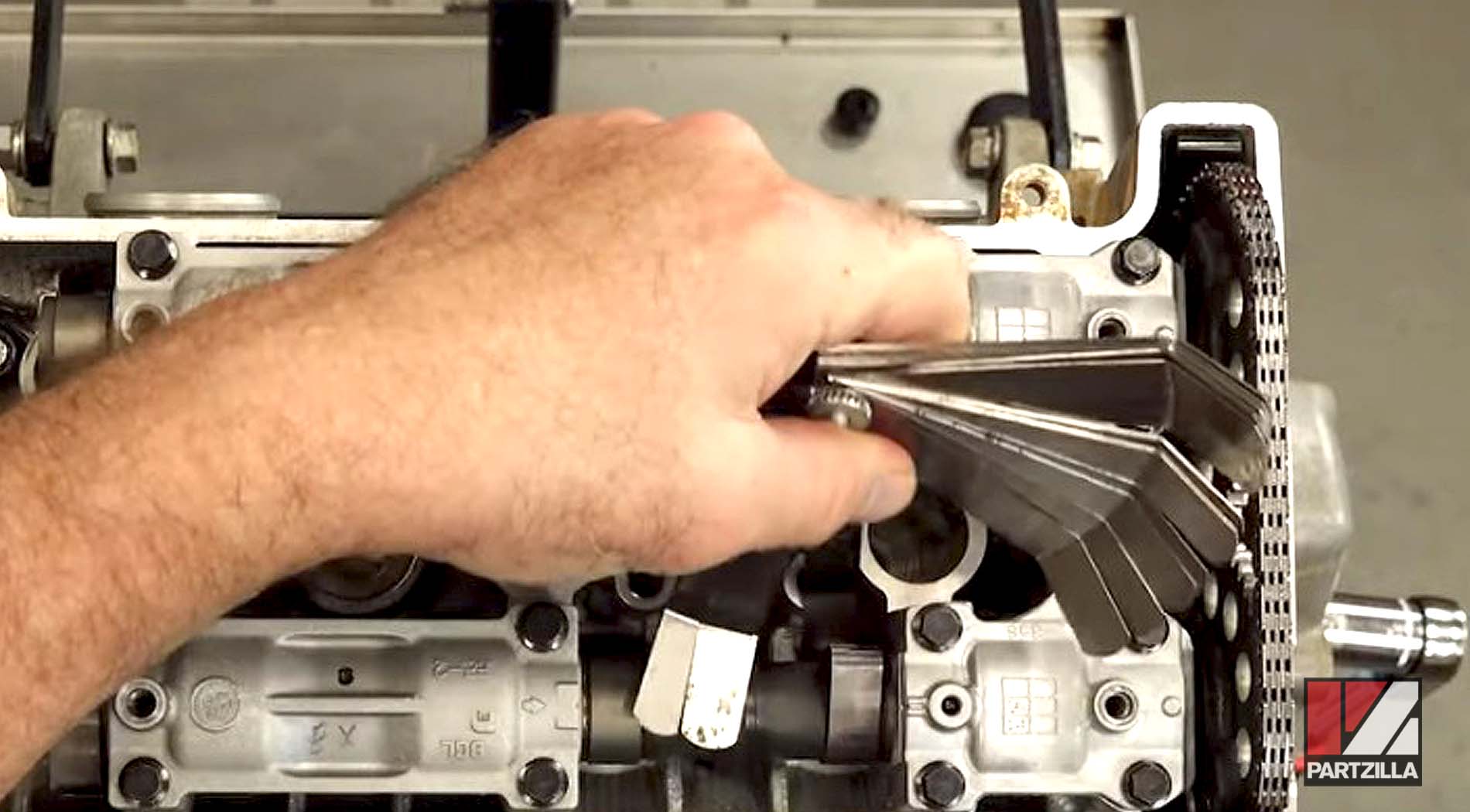
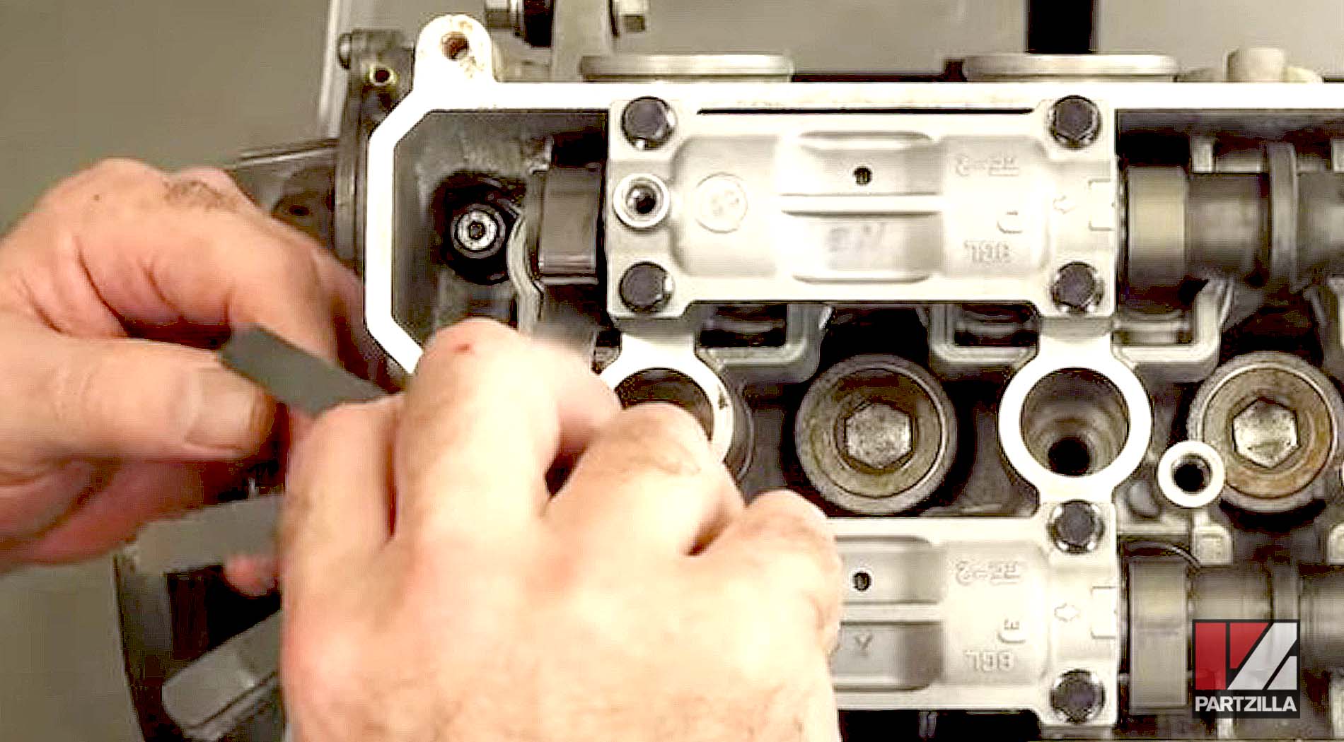
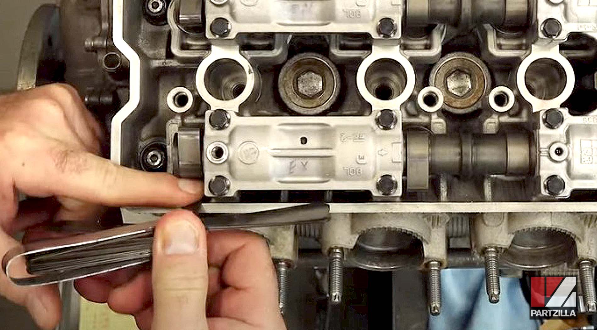
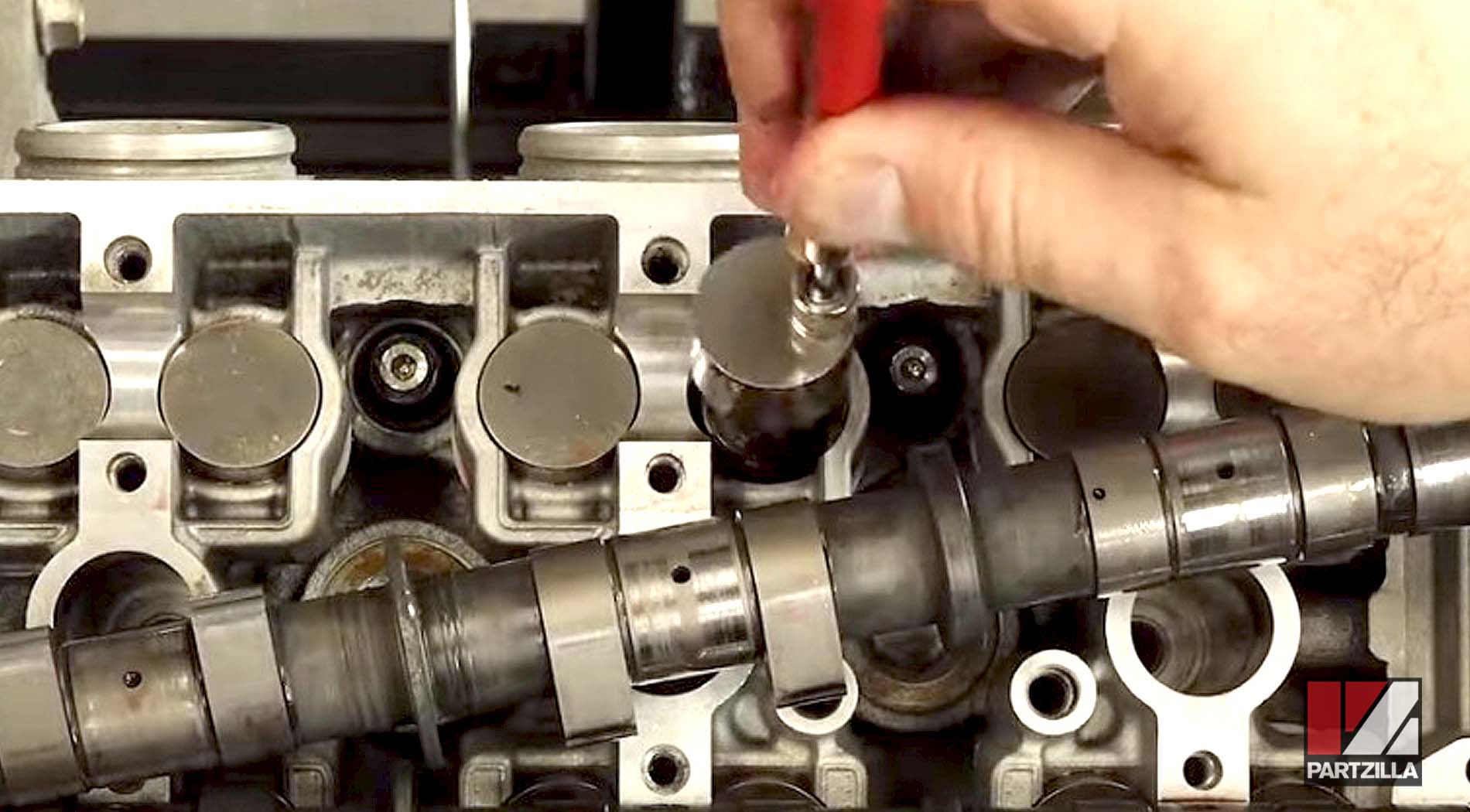
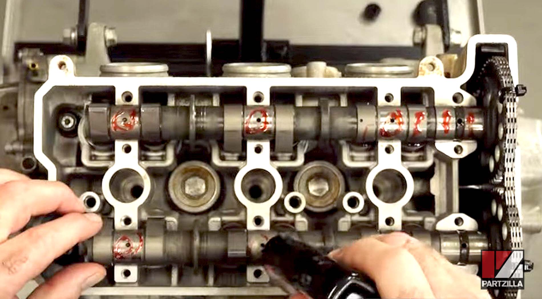
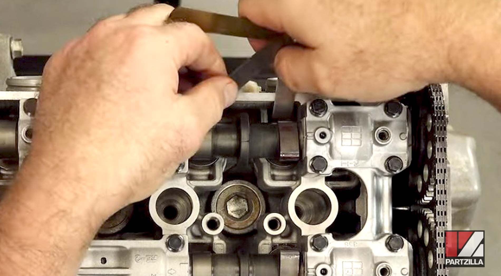
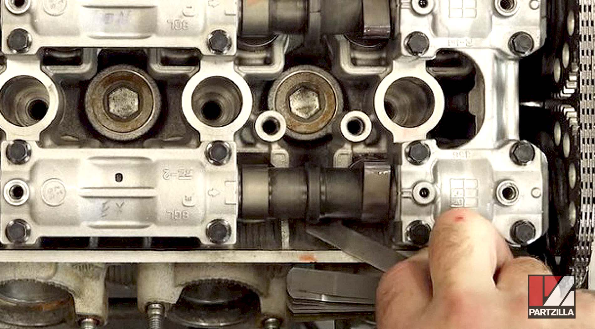
We then use a feeler gauge to measure the current valve clearance measurement for each intake and exhaust valve for reference.
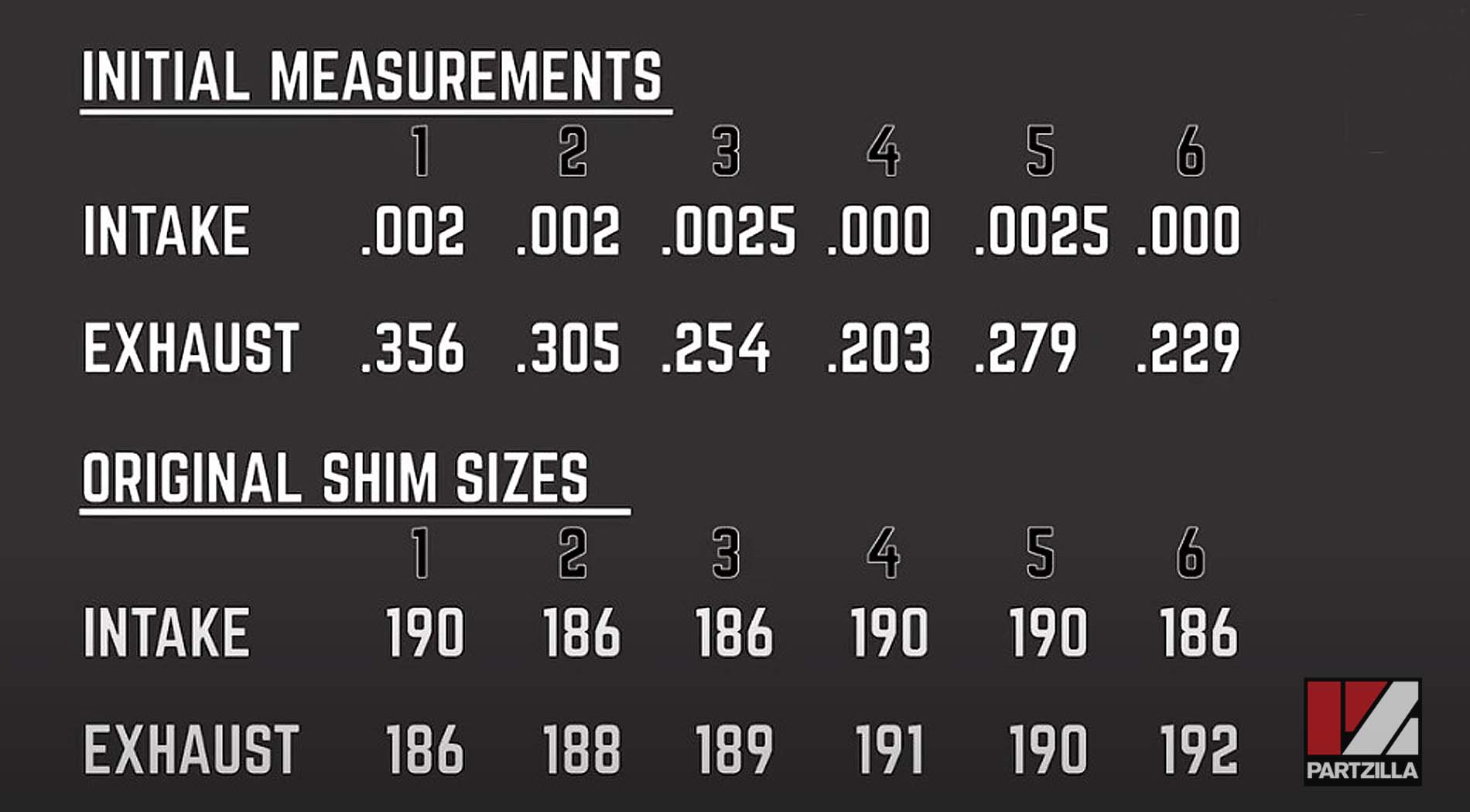
Our Valve Clearance Measurements
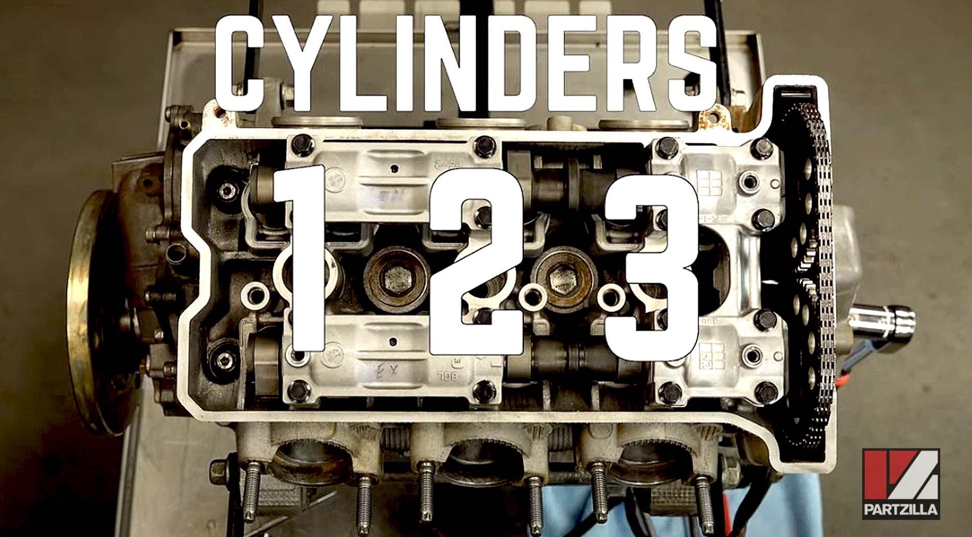
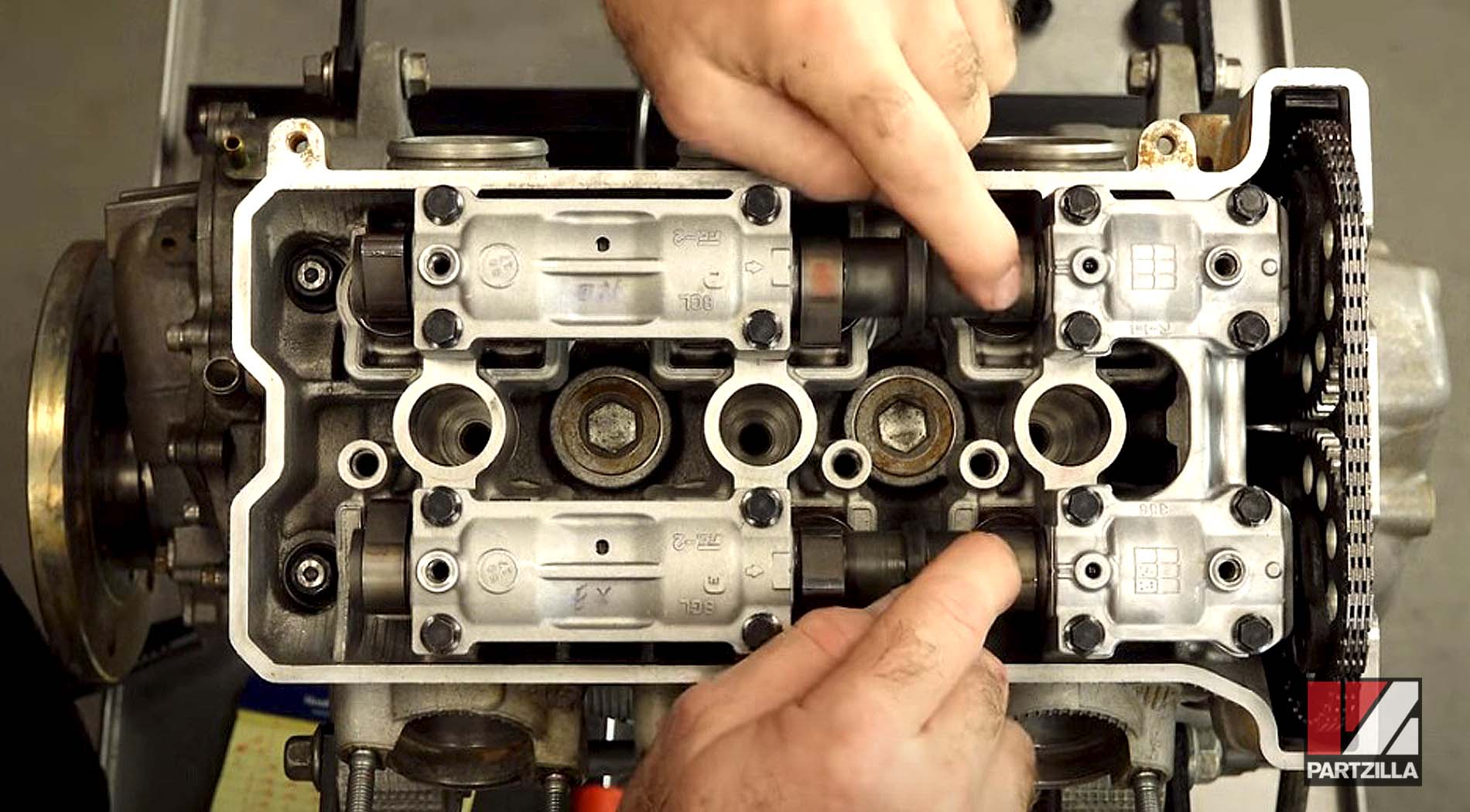
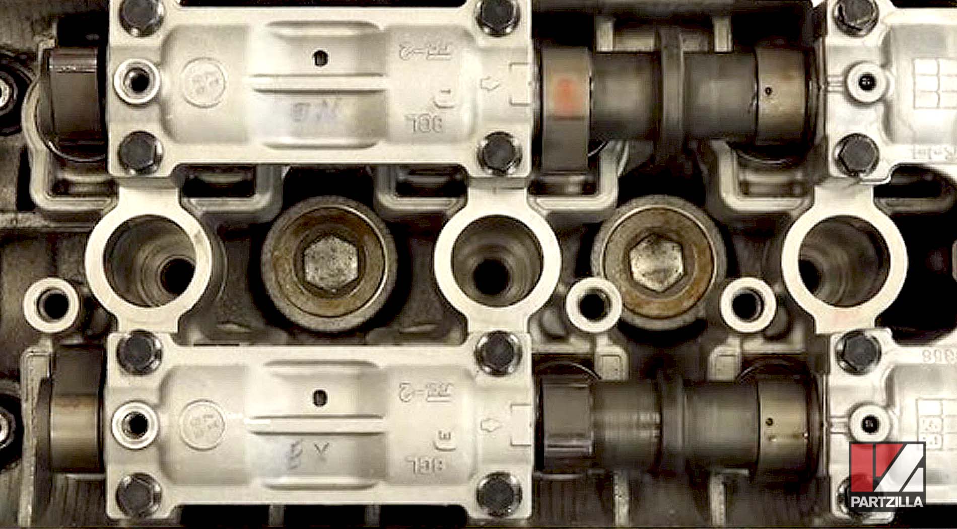
On cylinder number 3, on the intake side on position number 6, there was no clearance, so there was no point of reference to adjust it out.
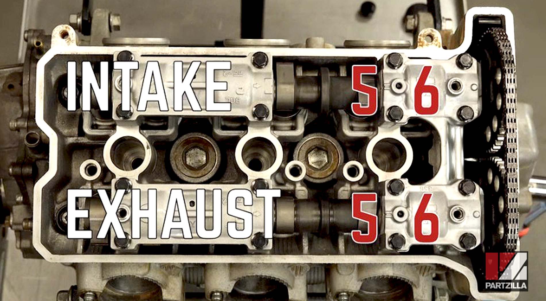
Because there was no clearance, we put in a value of 0 for that, and then adjust it accordingly. Number 5 has 0.0025mm. On the exhaust side for 5 and 6, we have .279mm and .229mm. We're going to rotate the crank 240° and then do cylinder number 1, then do 240° more and do cylinder number 2.
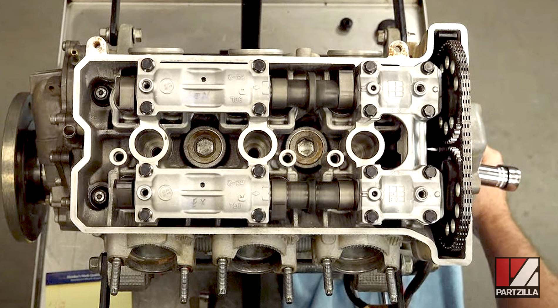
We want to watch the cams to get the lobes in the same position as number 3.
We then measure the clearance for all of the intake valves (1-6) and exhaust valves (1-6). After a little more rotating, we got the rest of our measurements and find that the only two valves that didn’t need to be readjusted are exhaust number 3 and exhaust number 6.
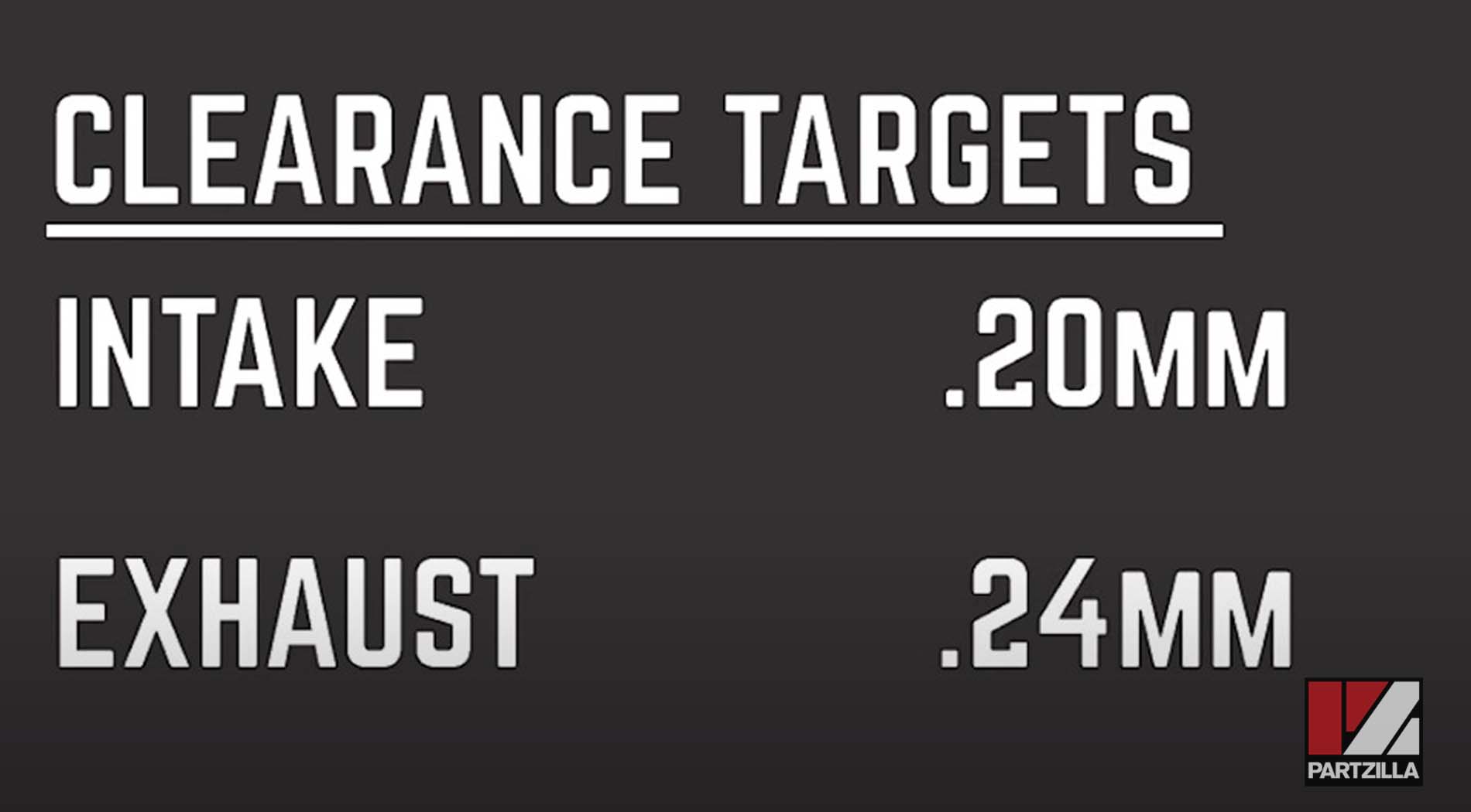
The Yamaha manual calls for a clearance range for the intake side of 0.15mm to .22mm. And the calculations in the manual use the 0.22 as the high side, as far as the adjustment point.
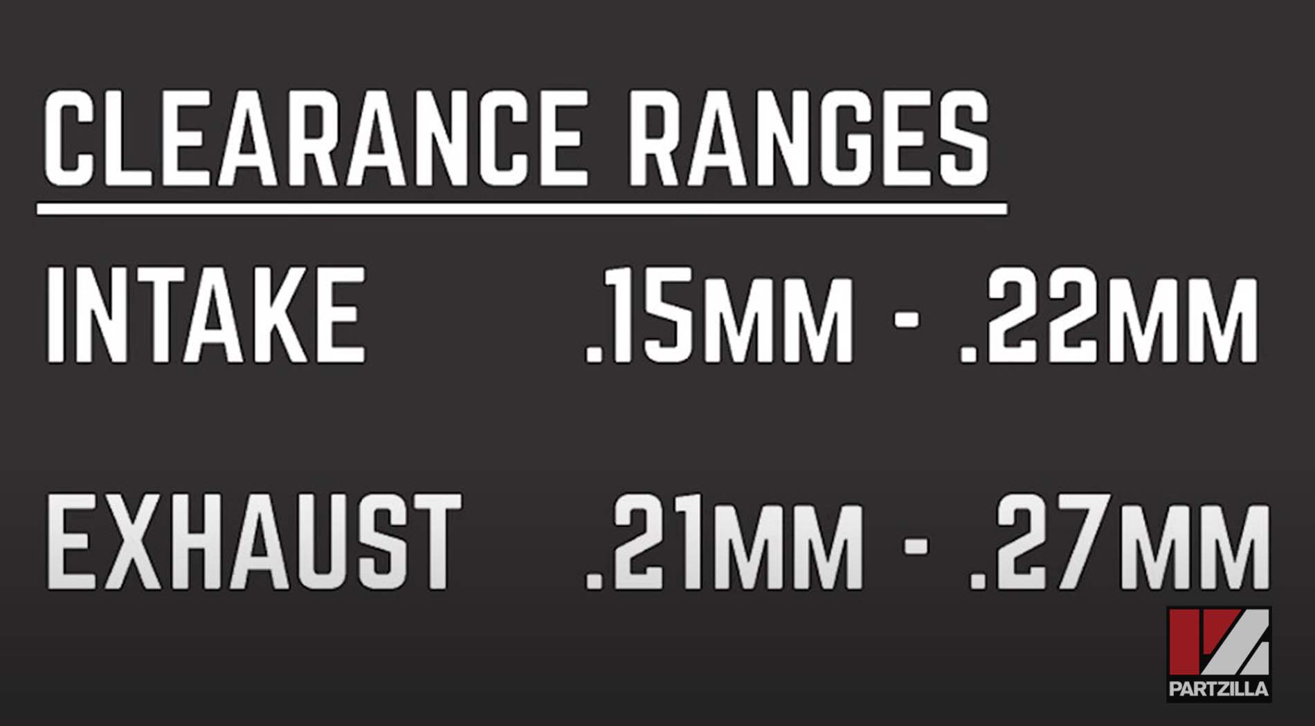
However, we have aftermarket Kibblewhite valves installed, so we don’t need to make that drastic of an adjustment. Instead, out of that range of .15 to 0.22, we’re aiming more in the middle, using .2 as the target for the intake side, and 0.24mm on the exhaust side.
The measurements on the intake side were all really small, even 0 in a couple of cases, so we may have to readjust once we’re closer to 0.2 clearance.
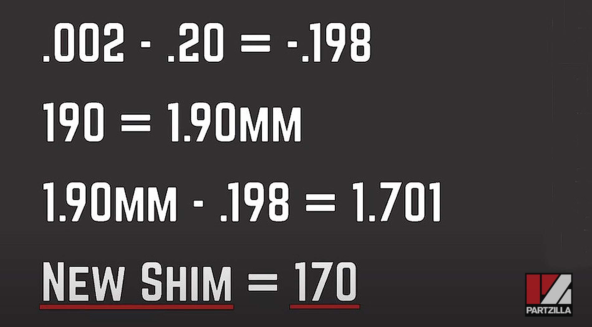
Here, we take that initial measurement of 0.002, and then subtract from the 0.2 target, which equals a change of .198mm. The initial thickness of that shim that we measured when we were putting it together was 1.90mm. So we need to take that 1.9mm, subtract out the .198, and that gives us 1.70mm rounded up for the new shim.
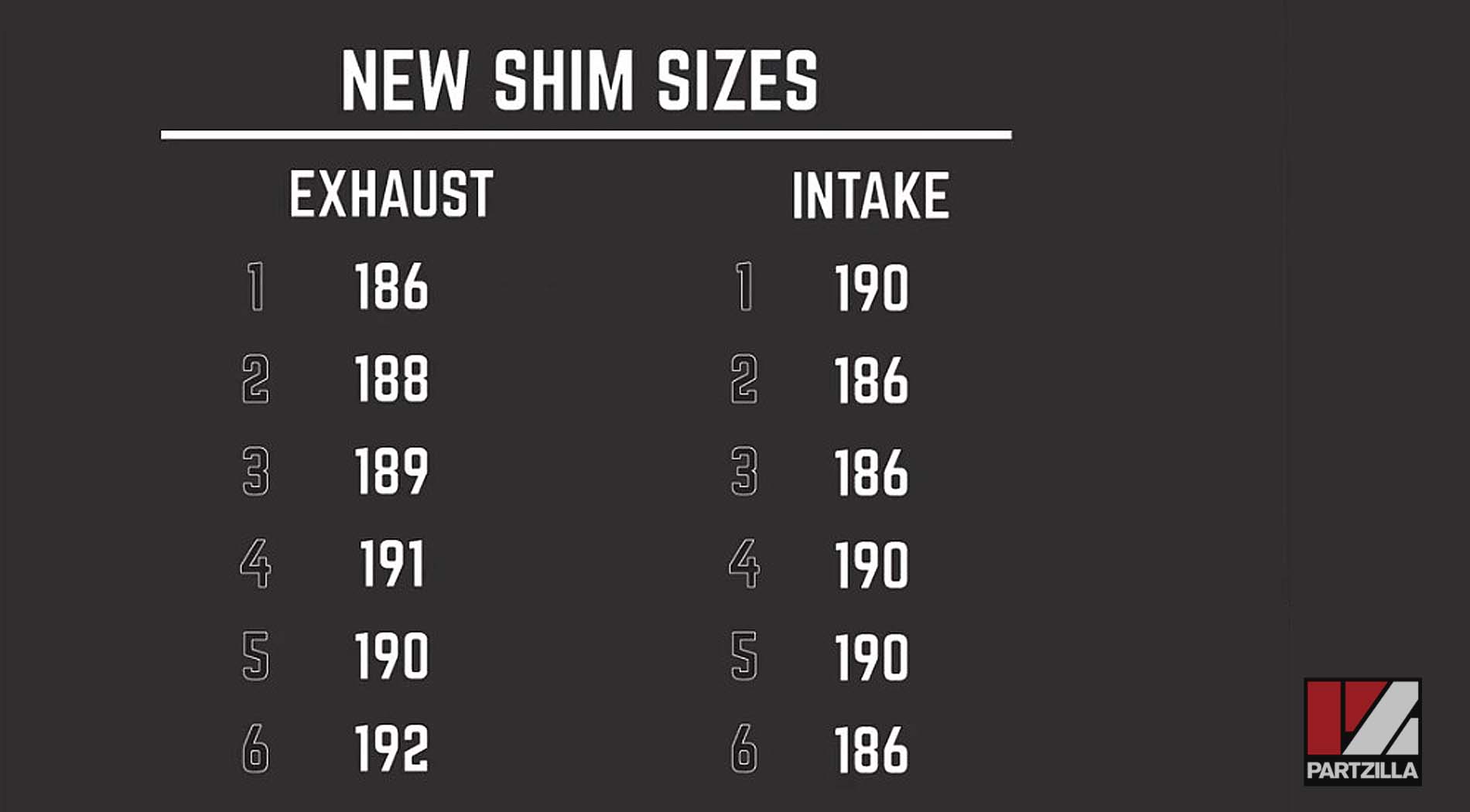
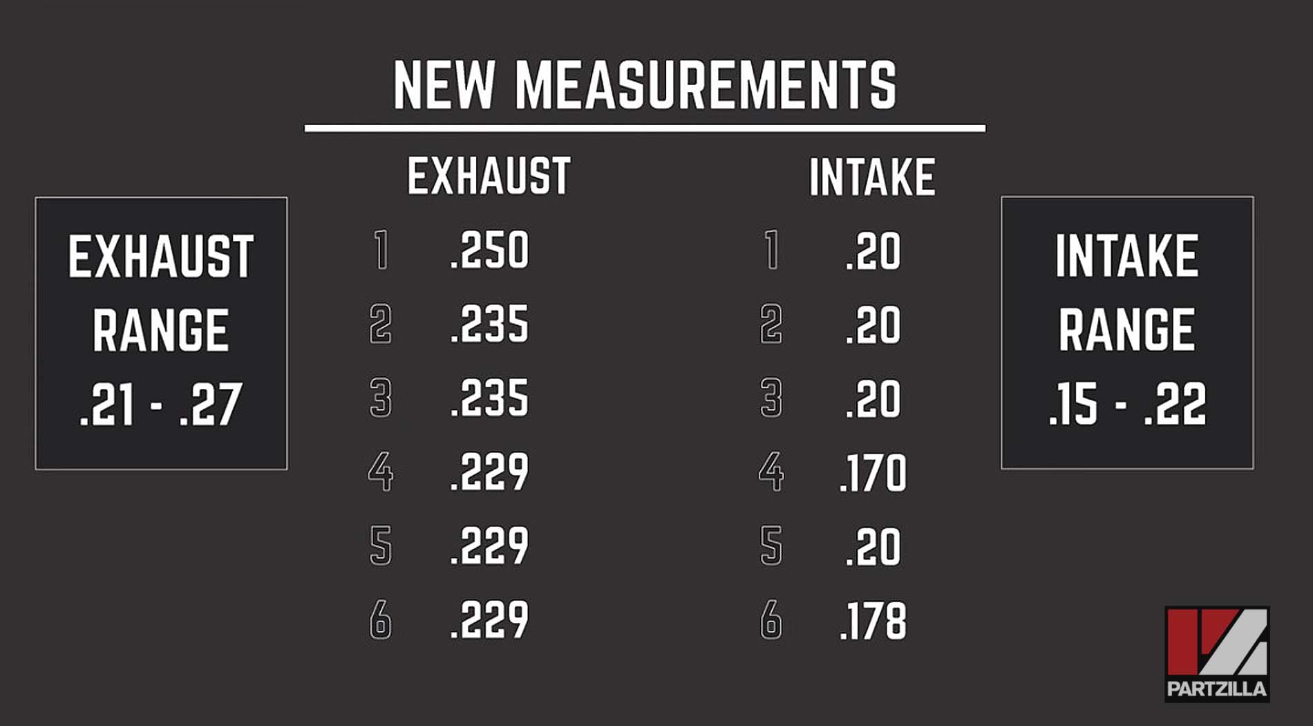
The measurements for our valve shim thickness ends up as follows:
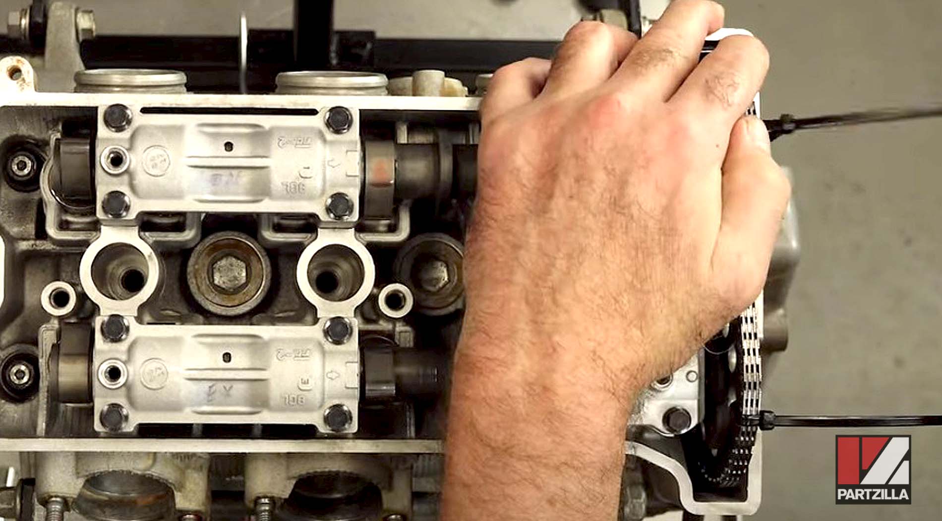
Now we bring around number 3 to the split overlap. So that's top dead center on compression stroke, but we want to bring it around 360° more to where we're at the split overlap. We line up on those marks, with the cams facing down, and the lobes and marks are where they're supposed to be.
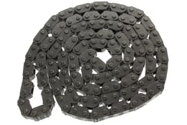
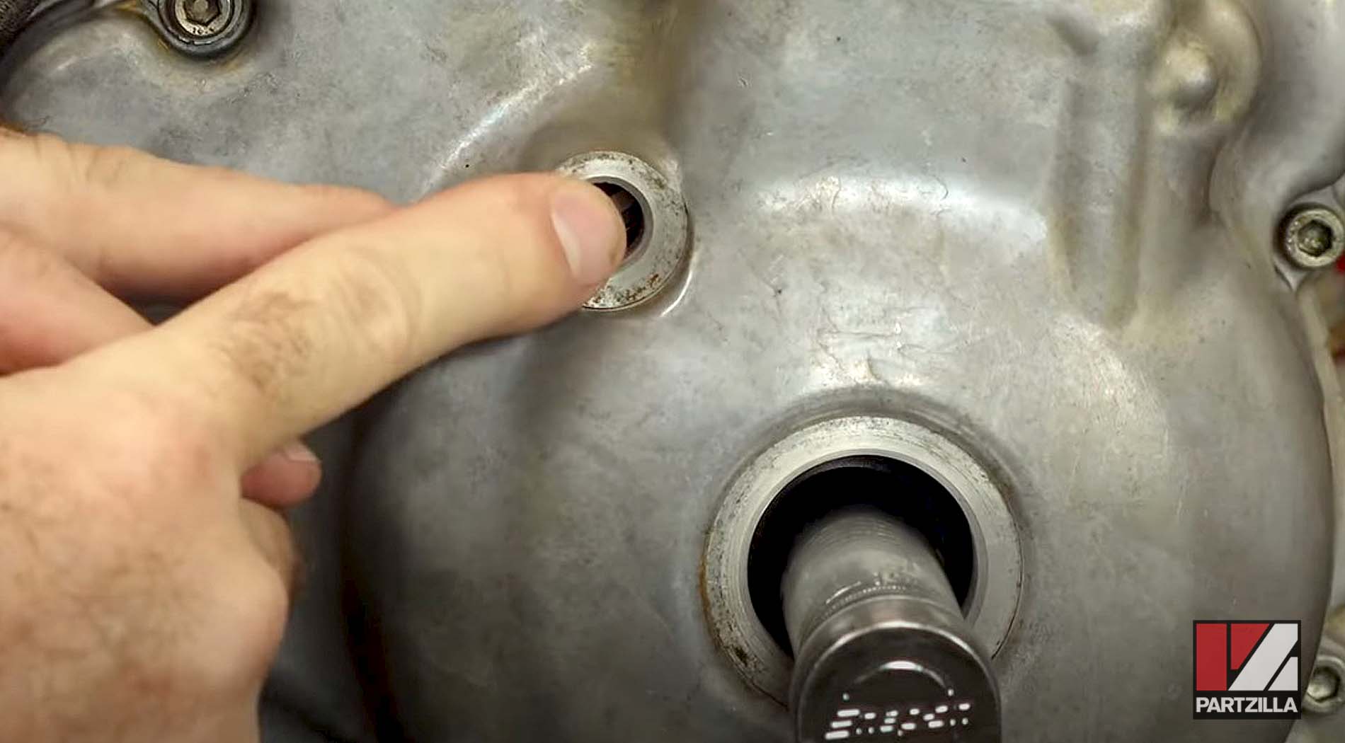
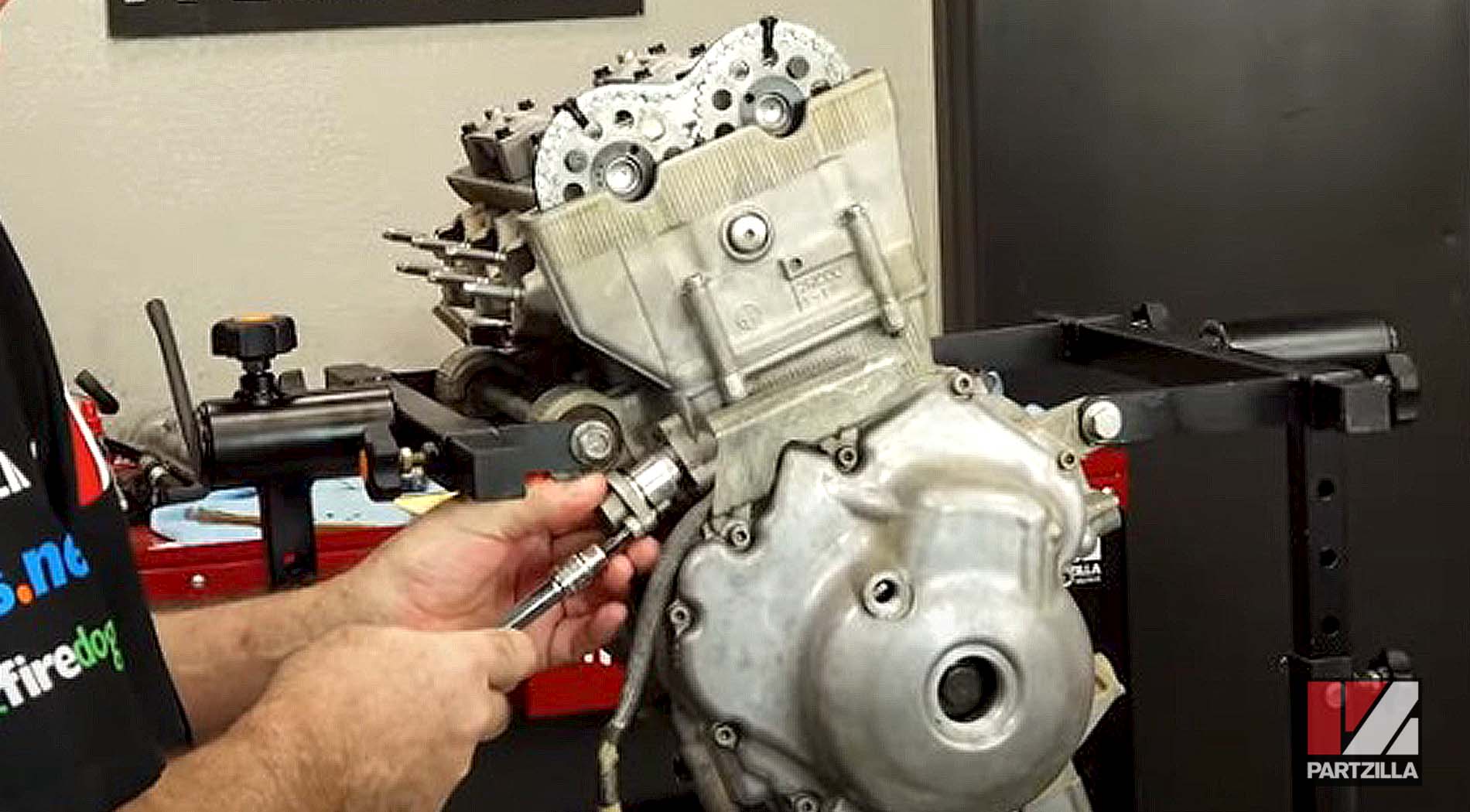
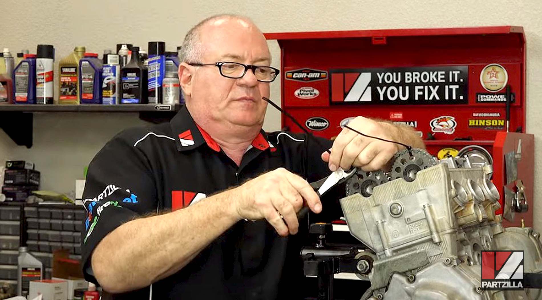
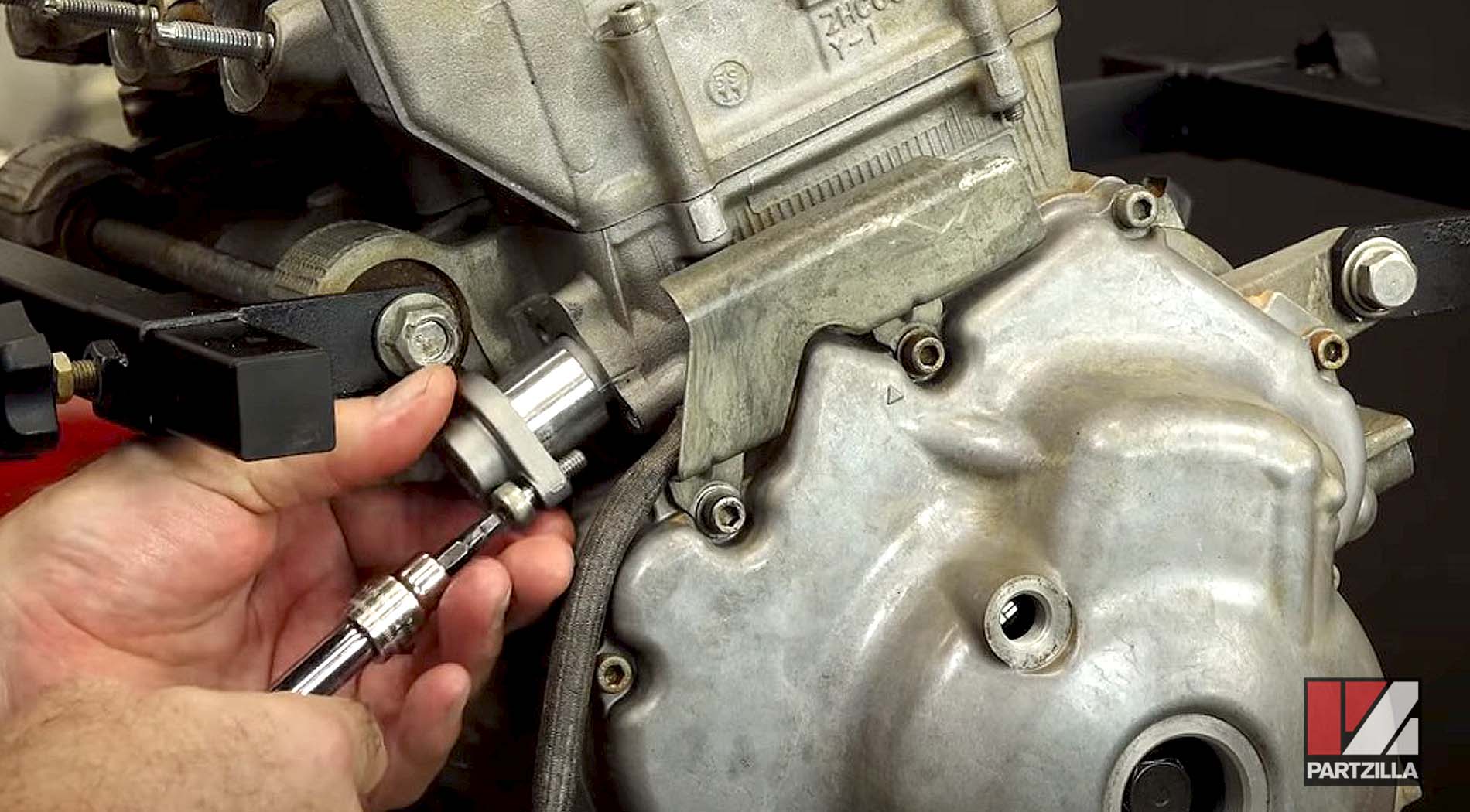
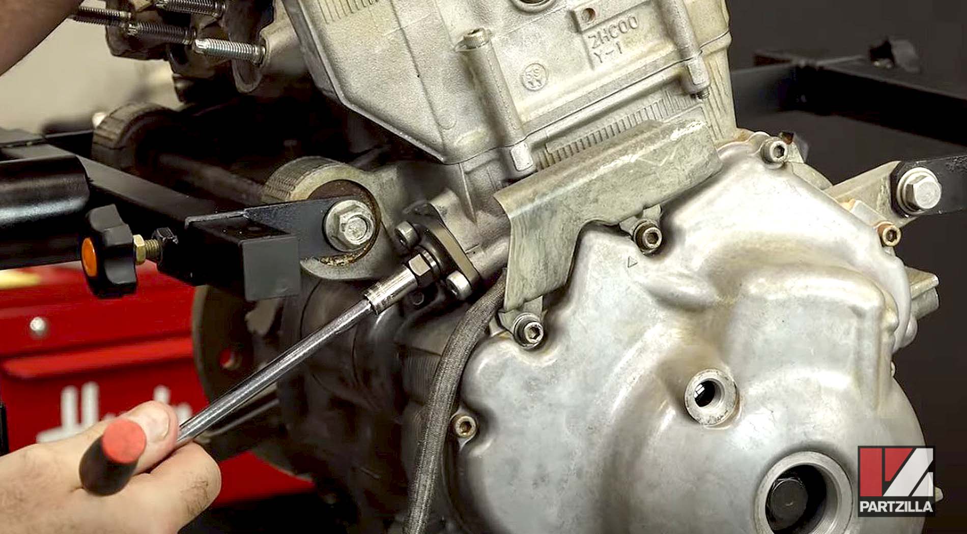
Next, we put on zip ties to hold the chain in place so it doesn’t jump time, then we can install the new chain tensioner and remove the caps.
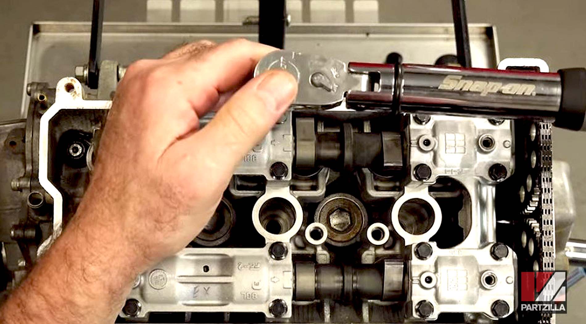
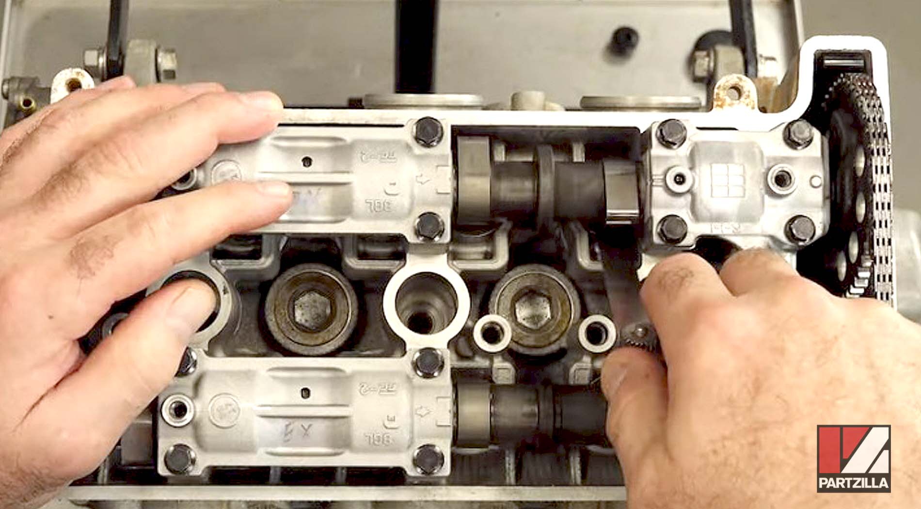
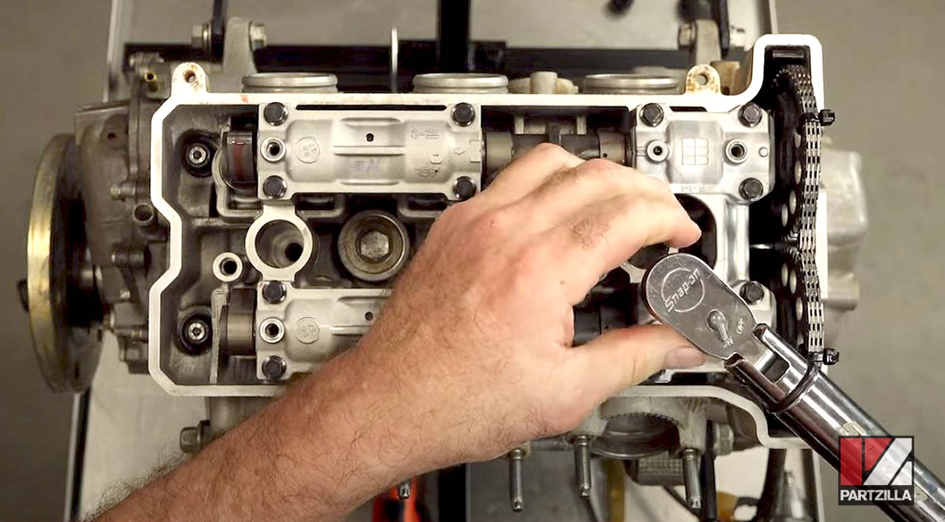
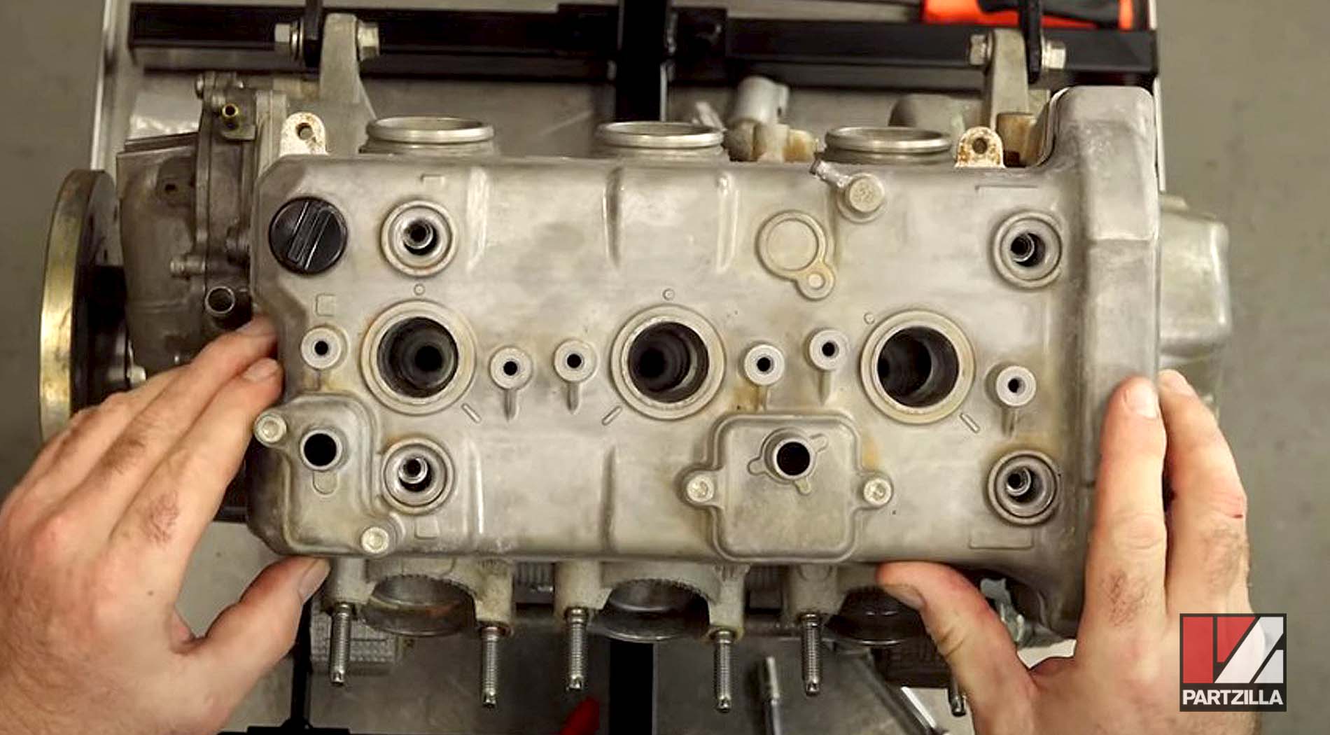
We remove the caps, then use a valve lifter to pull each tappet out one at a time, make the necessary adjustment for each tappet, then put it back and go to the next.
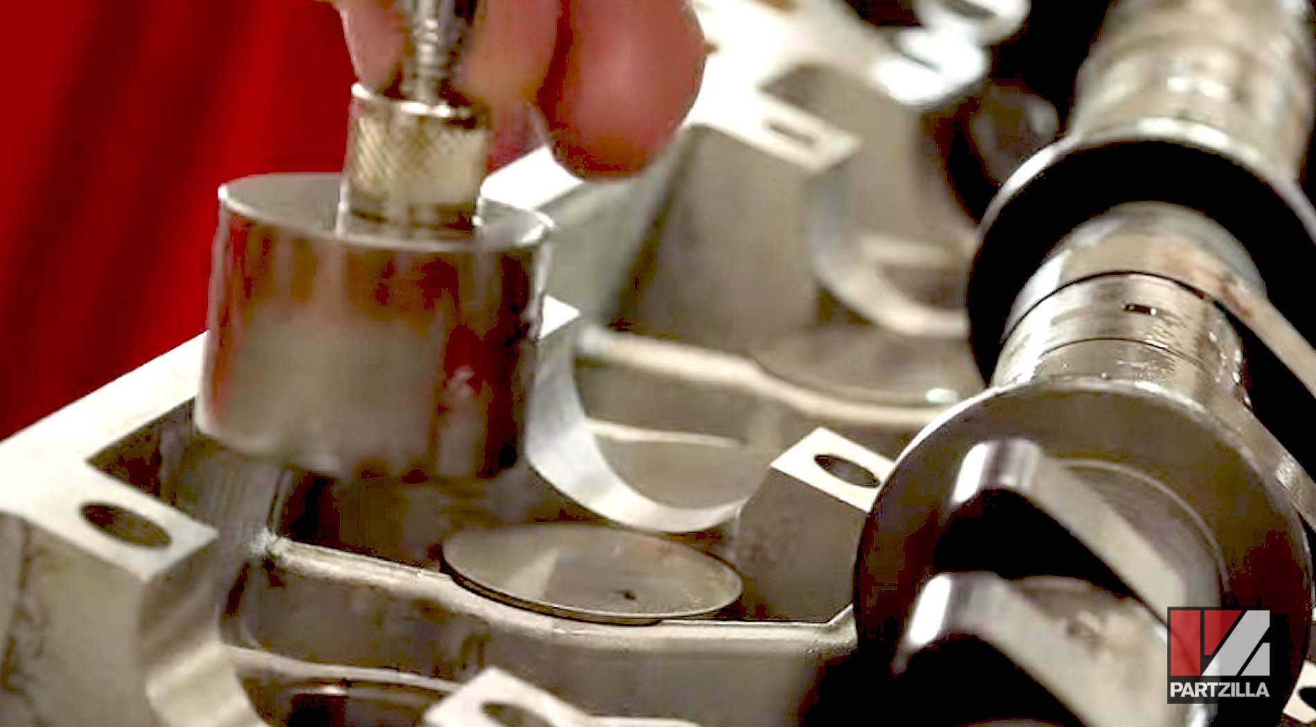
Once the shims are in place, we put the caps back on, cut the zip ties loose, add some assembly lube, put the caps back on and measure it one more time to see if there are any other adjustments that need to be made.
We tighten the caps in a crisscross pattern to get them snugged down evenly, then we go back and torque them to 7.2 foot-pounds, starting in the middle and working our way to the front and the back.
Next, we bring the engine around to top dead center on the compression stroke and use the feeler gauge to take new valve clearance measurements on both the intake and exhaust sides.
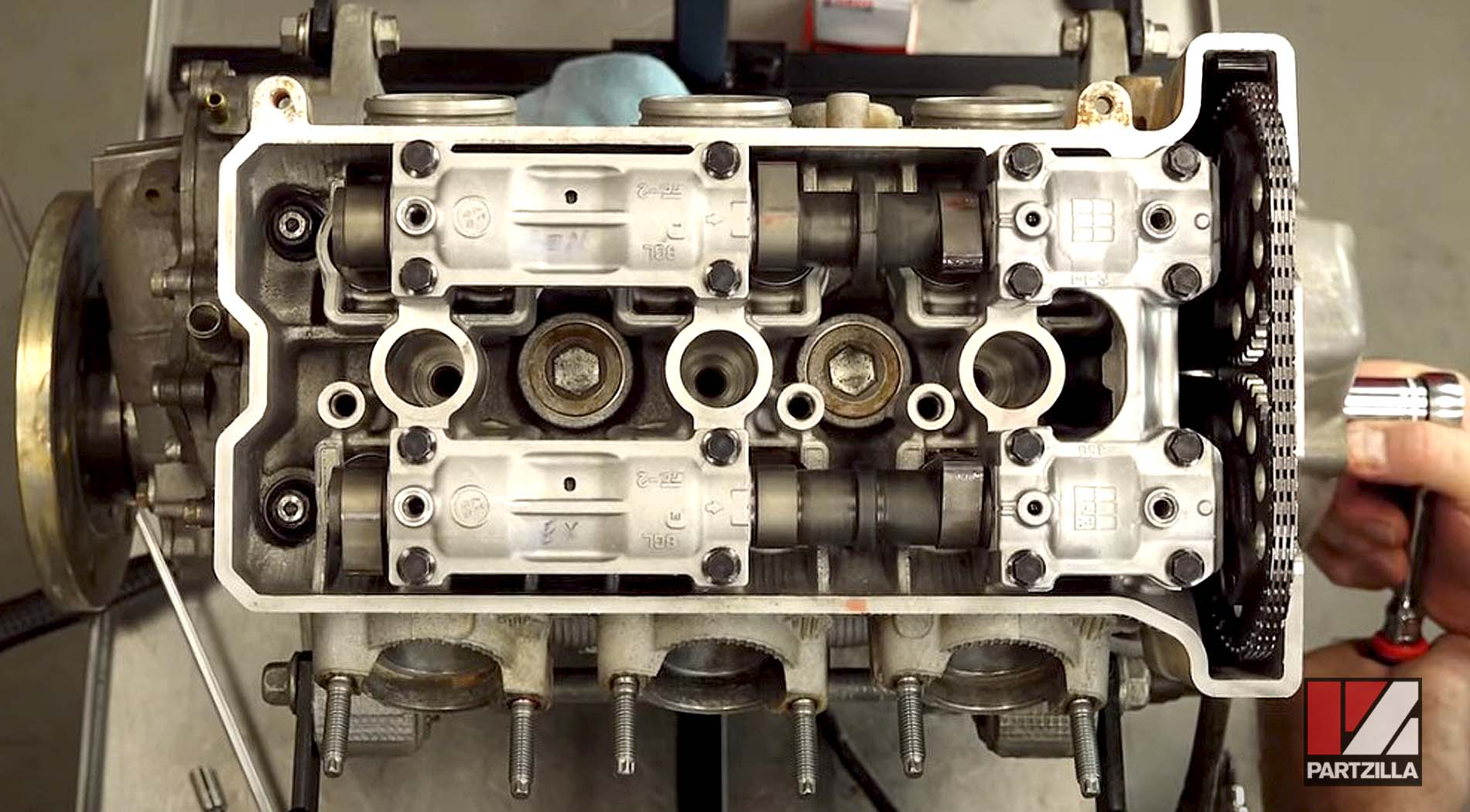
We went through and measured everything, and got everything within spec, with our new measurements shown in the chart below.
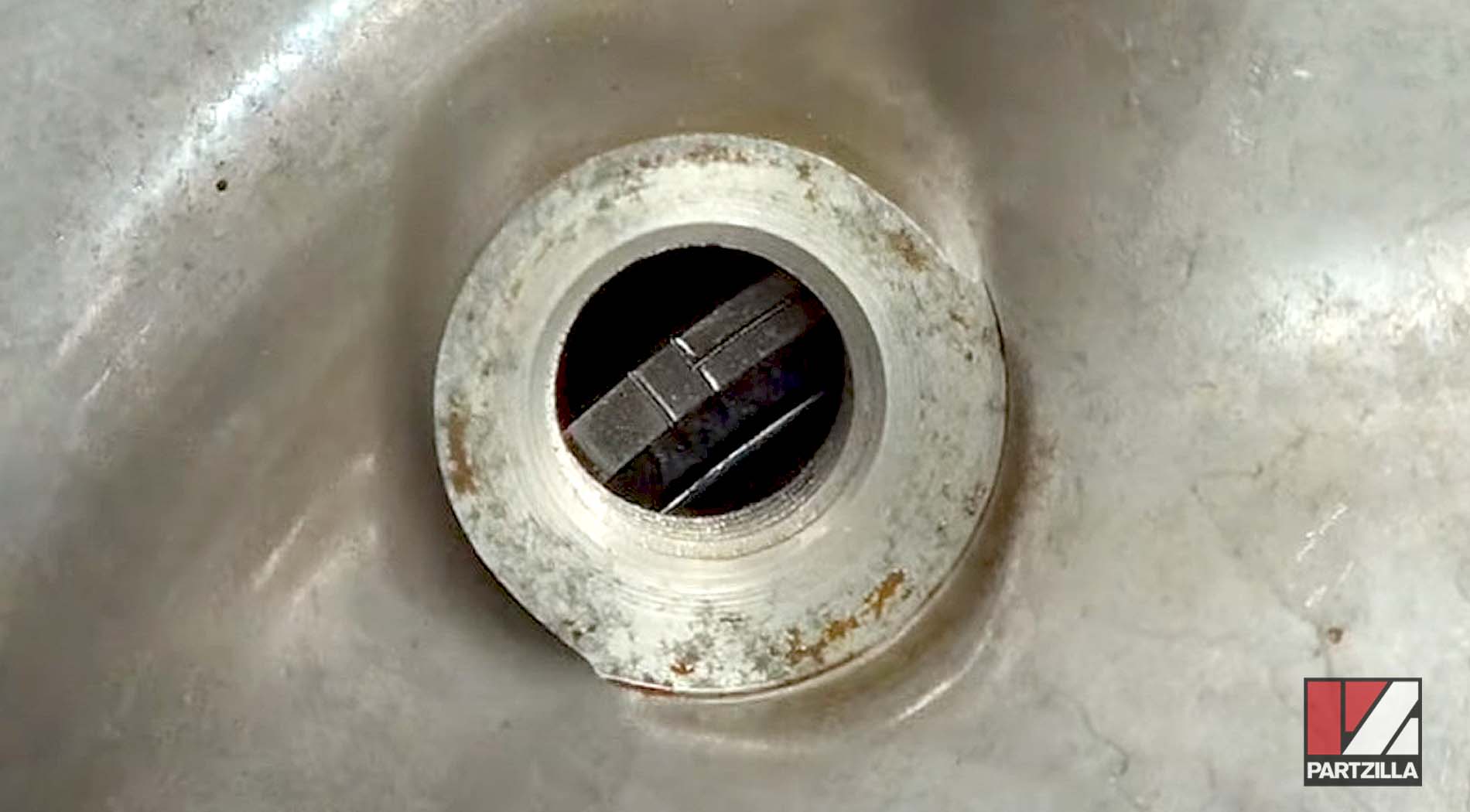
Next, we remove the OEM tensioner and replace it with an aftermarket manually adjustable tensioner.
NOTE: When changing out chain tensioner, make sure you put in a new tensioner case gasket.
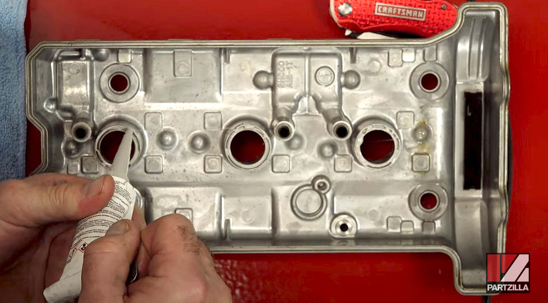
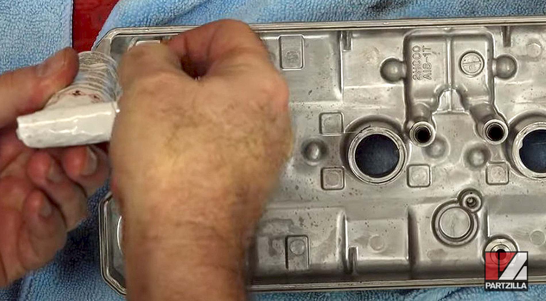
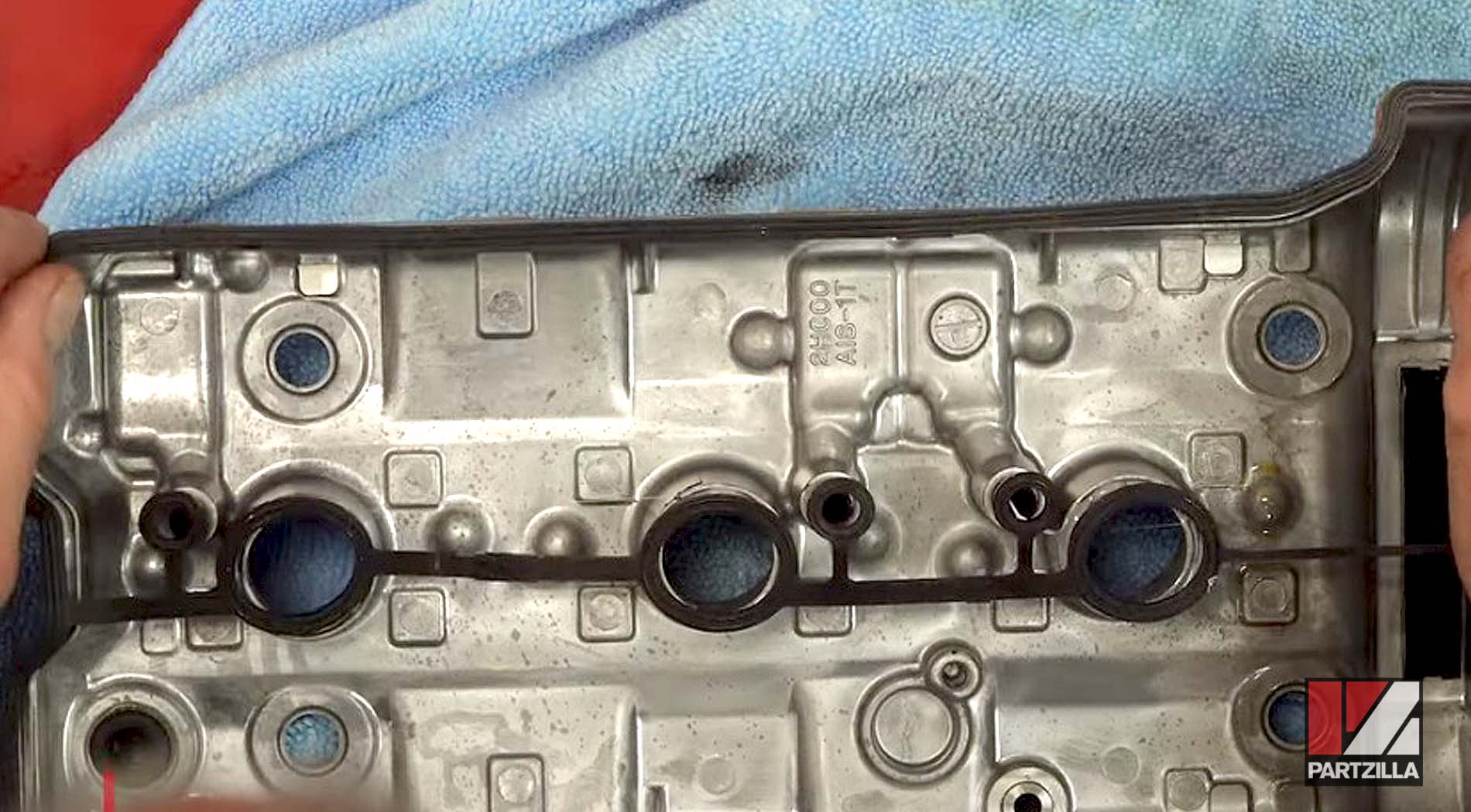
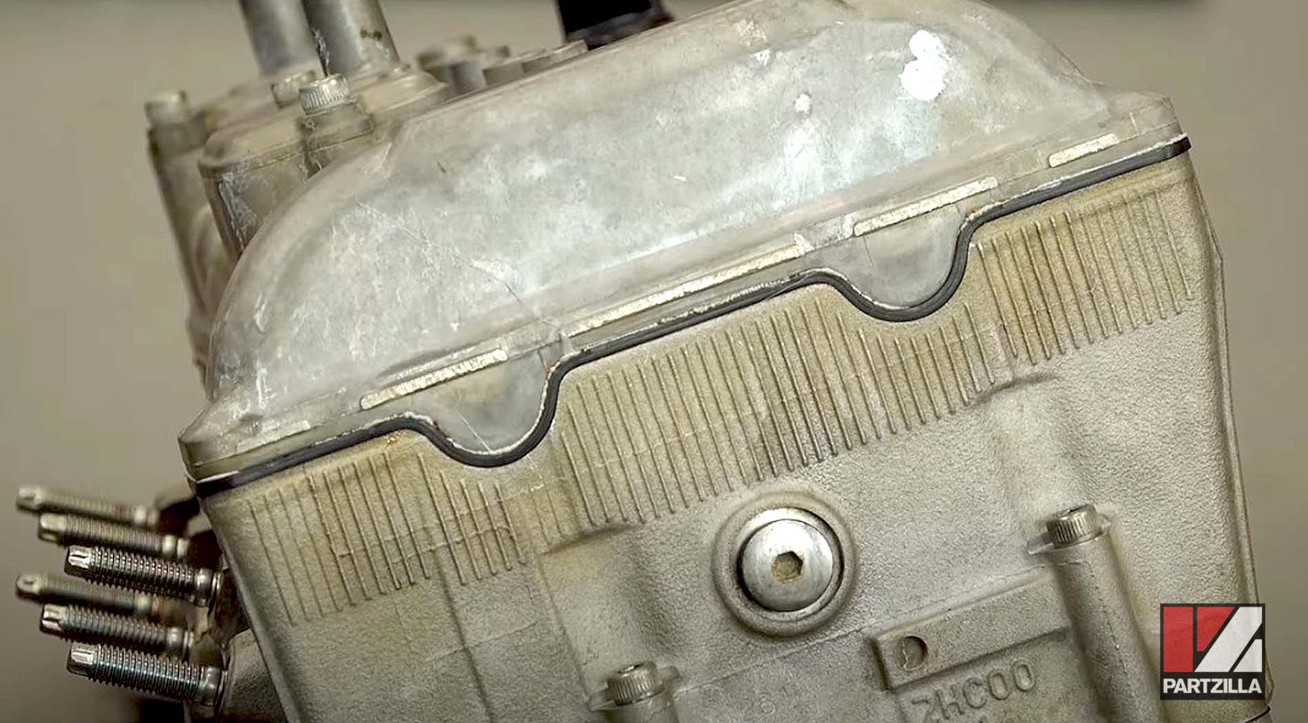
With the valves adjusted and the new chain tensioner installed, all that’s left is to install the valve cover and some new spark plugs. For the valve cover, we apply a thin bead of ThreeBond liquid gasket around all of the channels and the edge of the cover before installing the head cover gasket.
We get the valve cover closed up, then install the washers on top, which have seals built into them, and torque them to 7.2 foot-pounds.
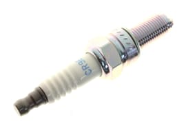
Finally, we install new spark plugs and torque them to 9.4 foot-pounds.
There’s more work to do on this Yamaha YXZ1000R, since we’re doing a turbo upgrade on it. Watch the playlist below to keep up with everything we worked on for this UTV’s engine rebuild.