Honda Grom Engine Management Upgrades
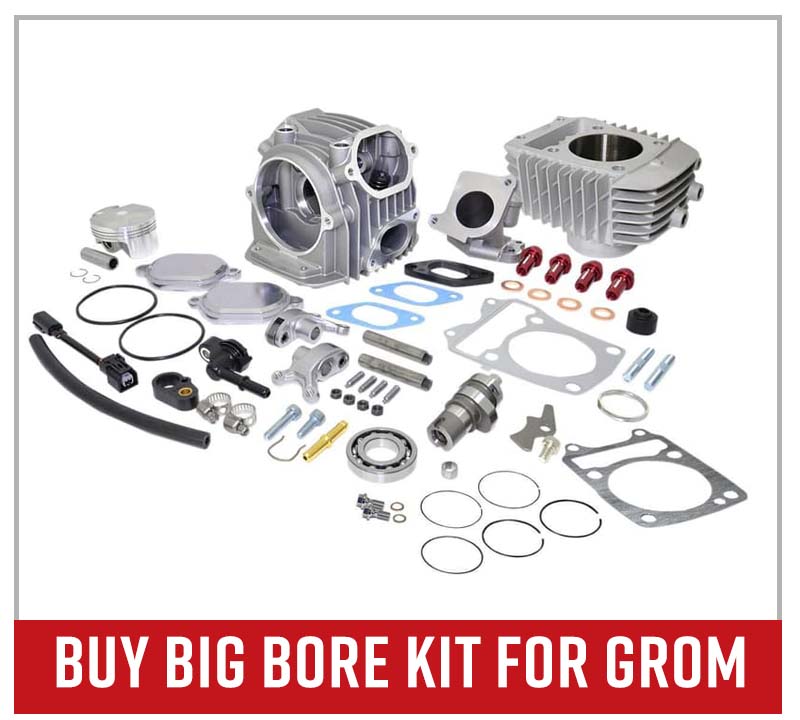
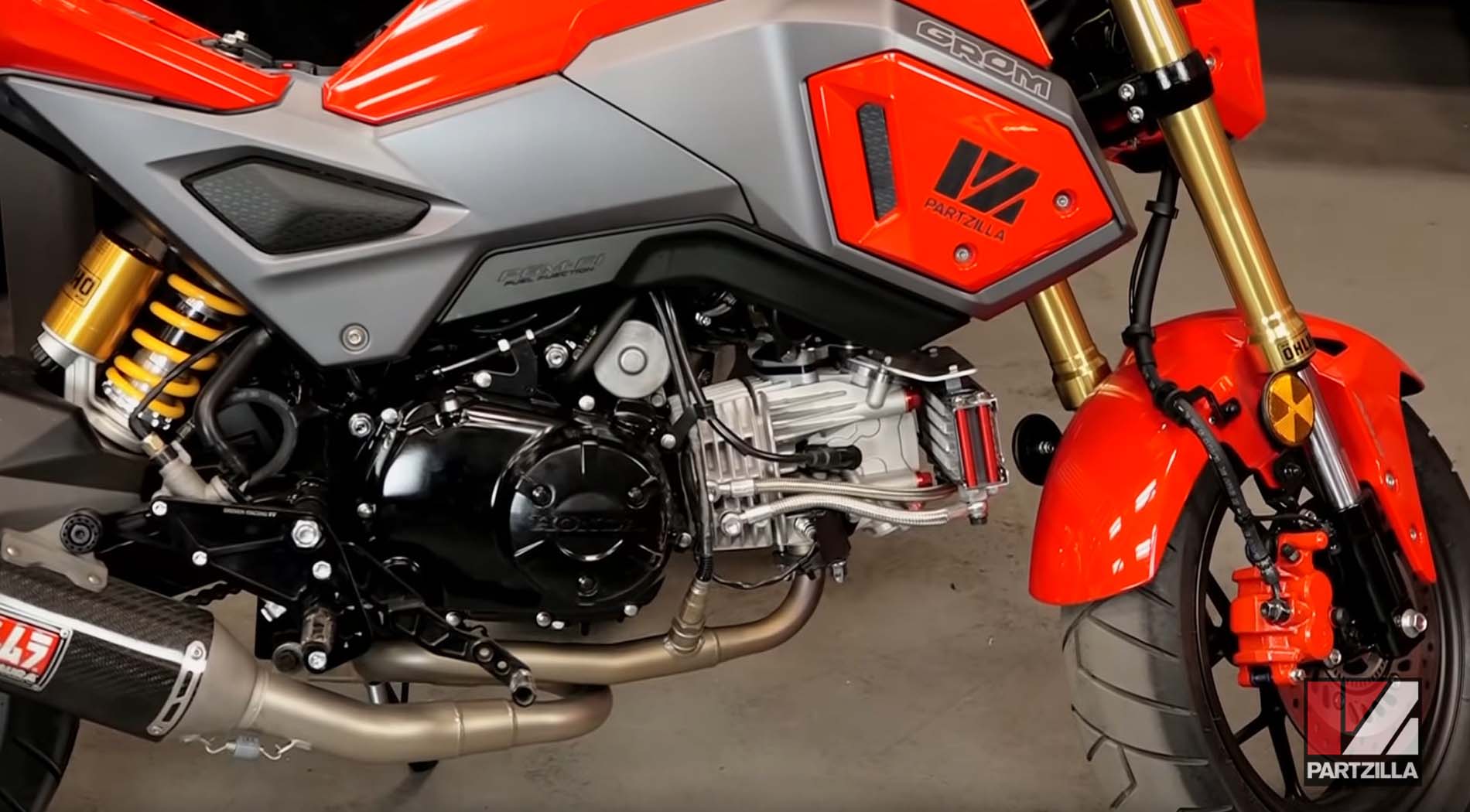
We went a long way upgrading our 2018 Honda Grom 125 with aftermarket parts. Alongside a host of cosmetic improvements, including a KOSO big bore kit and a Yoshimura exhaust system.
Our Honda Grom aftermarket upgrades project spanned a multitude of videos before we strung the entire project together into the video above. To get all these new parts to work together, we also installed engine management hardware to ensure everything operates at its peak. Watch the video above and read the steps below to see what final upgrades we did on the Grom before we gave it away.
Tools and Parts – Honda Grom Aftermarket Upgrades
- Ratchet and sockets
- 6mm Allen
- Wire crimp tool
- Laptop
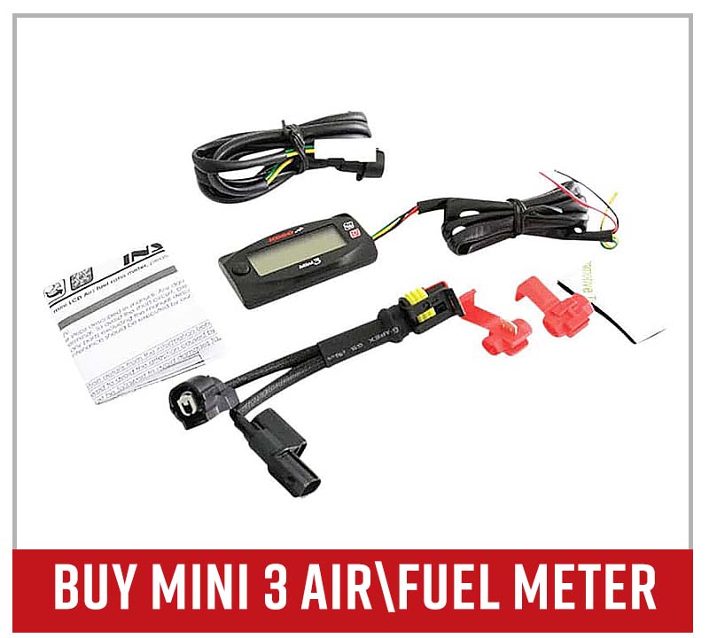
Part 1: Installing KOSO Mini3 Air/Fuel Ratio Meter
The KOSO Mini3 air/fuel meter mounts inside the KOSO top clamp bracket, then the combined assembly is mounted on top of the handlebars, where they replace the original handlebar mounts.
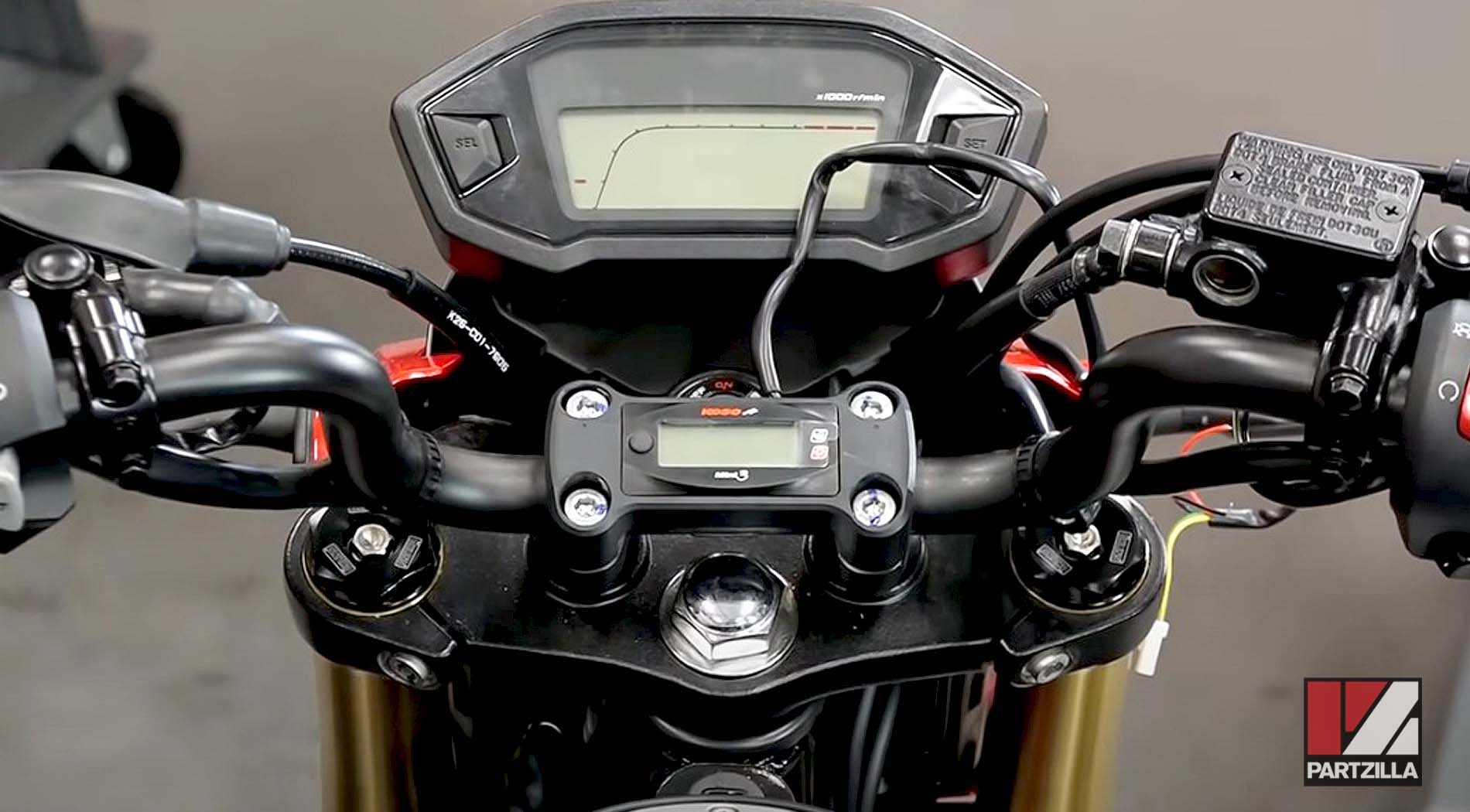
Once mounted, the wires for the KOSO Mini3 will be run forward and spliced into an ignition source and a ground source running from the ignition switch wiring harness.
PRO TIP: Always splice into wires on the switch side of an electrical connector and never the main wiring harness side. This way if anything goes wrong, you only have to replace the switch and not the entire main wiring harness.
Watch the clip below to see the KOSO Mini3 installation and wiring instructions segment of our Honda Grom Aftermarket Upgrades video.
Part 2: Installing DynoJet Wideband O2 Sensor
Installation of the DynoJet Wideband O2 sensor into the sensor bay in the exhaust pipe, and the DynoJet Wideband control unit in the cavity within the frame beside the battery.
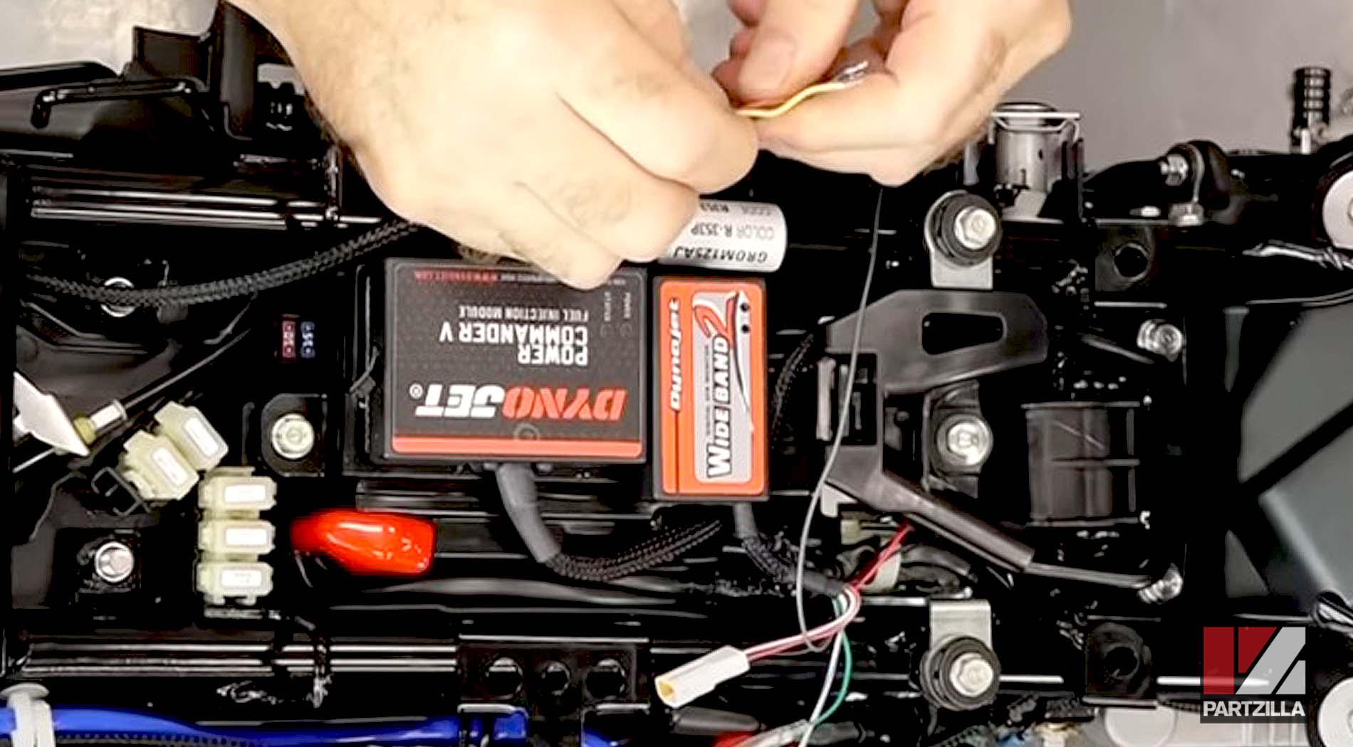
NOTE: Don’t touch the tip of the O2 sensor. Leave the protective cap on until you're ready to install it.
Watch the clip below to see the DynoJet Wideband installation and wiring instructions segment of our Honda Grom Aftermarket Upgrades video.
Part 3: Installing DynoJet Power Commander V Fuel Injection Module
DynoJet Power Commander V fuel injection module in the cavity within the frame beside the battery and the DynoJet Wideband control.
Disconnect the ECU harness from the main wiring harness and connect the DynoJet Power Commander V cable so it’s in line with the ECU and main wiring harnesses.
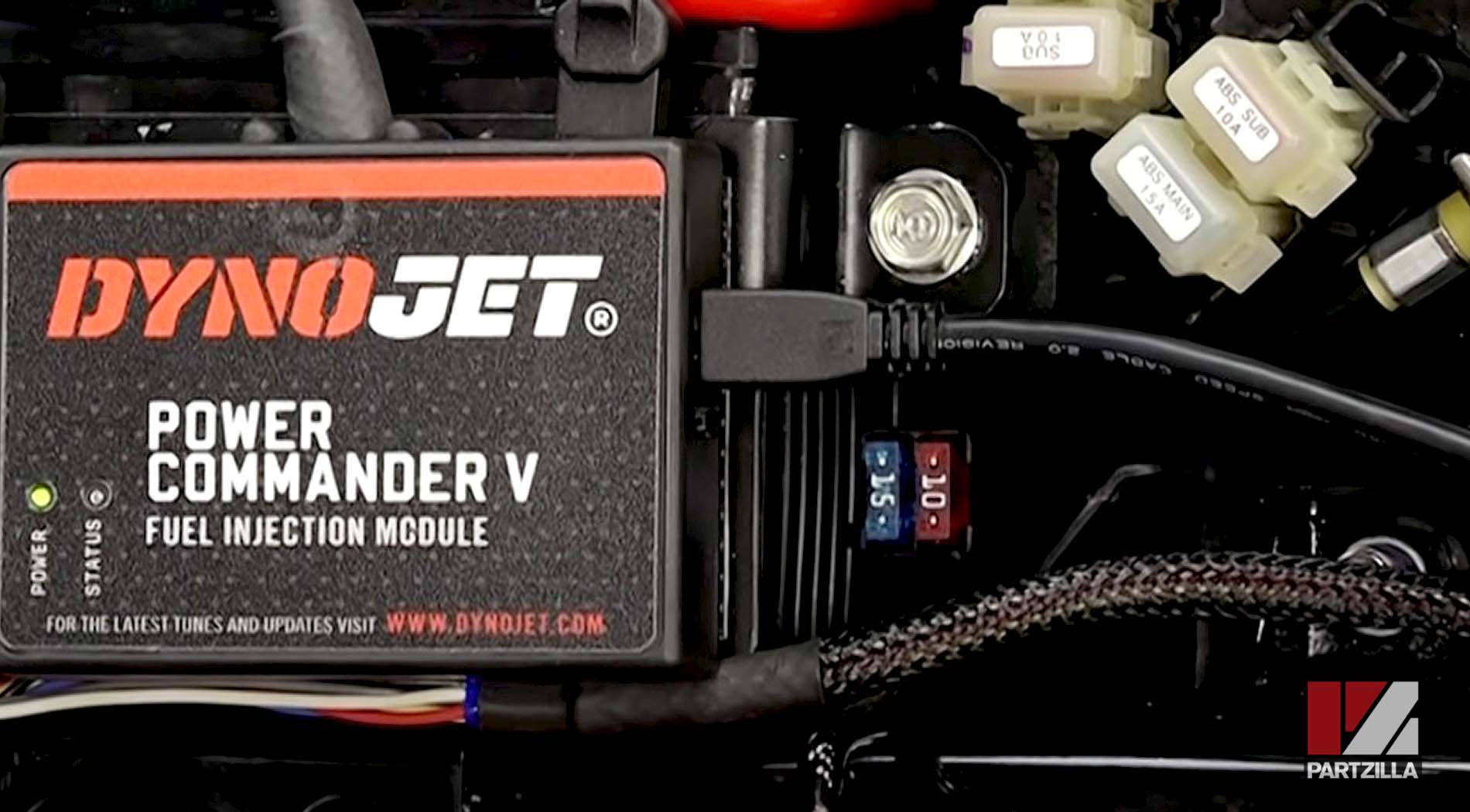
Watch the clip below to see the DynoJet Power Commander V installation and wiring instructions segment of our Honda Grom Aftermarket Upgrades video.
Part 4: Programming the DynoJet Power Commander V Software
Installation of the DynoJet Power Commander V software onto a laptop that connects to the Power Commander V unit. You can find several maps on the DynoJet website.
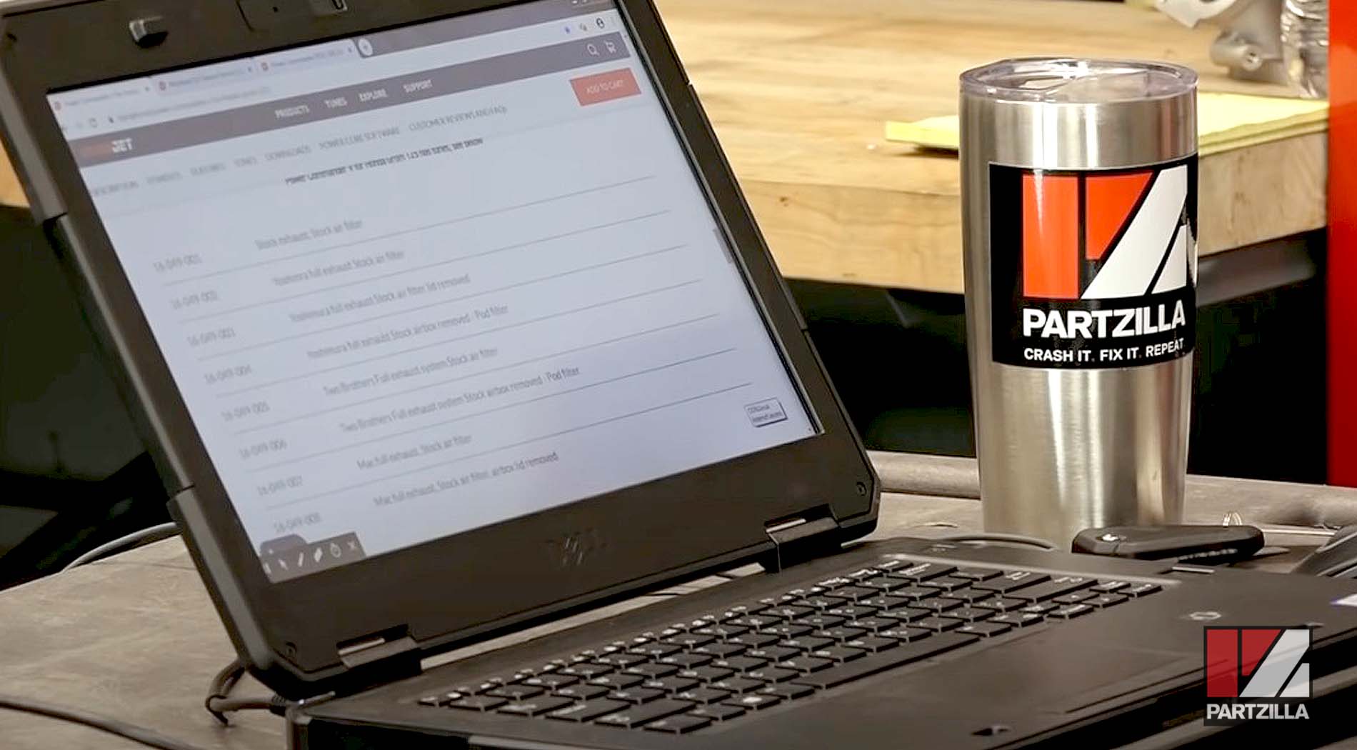
Because our Honda Grom upgrade project went far beyond a typical rebuild, DynoJet suggested we take one of their maps, zero it out and then choose our own air/fuel targets using the lambda AFR target.
NOTE: You’ll need to instruct the DynoJet Power Commander V software that you’re using a DynoJet Wideband.
Watch the clip below to see the DynoJet Power Commander V software programming instructions segment of our Honda Grom Aftermarket Upgrades video.
