How to Replace Yamaha YXZ1000R Wheel Bearings
Unusual noises coming from a Yamaha YXZ1000R side-by-side's wheels is a sure sign the bearings are worn and need replacing.
Watch the video above and follow the steps below to learn how to replace the front wheel bearings on a Yamaha YXZ1000R.
Tools and Parts – Yamaha YXZ1000R Wheel Bearing Replacement
- Ratchet and extensions
- 4mm, 10mm, 14mm, 17mm, 19mm, 22mm, 32mm sockets
- Hammer
- Flat-blade screwdriver
- Torque wrench
Removing Yamaha YXZ1000R Steering Knuckle Assembly
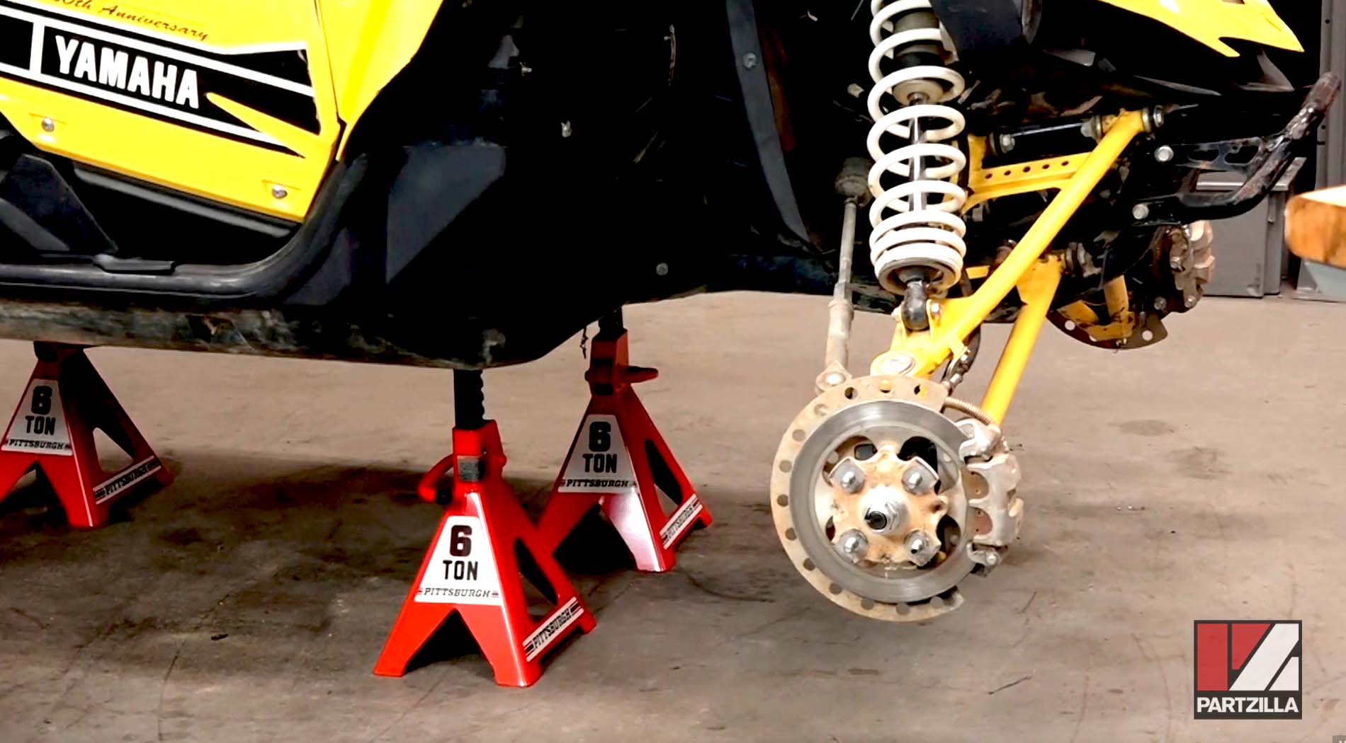
Step 1. Raise the vehicle and support it on axle stands positioned under the frame, then remove the rear wheels.
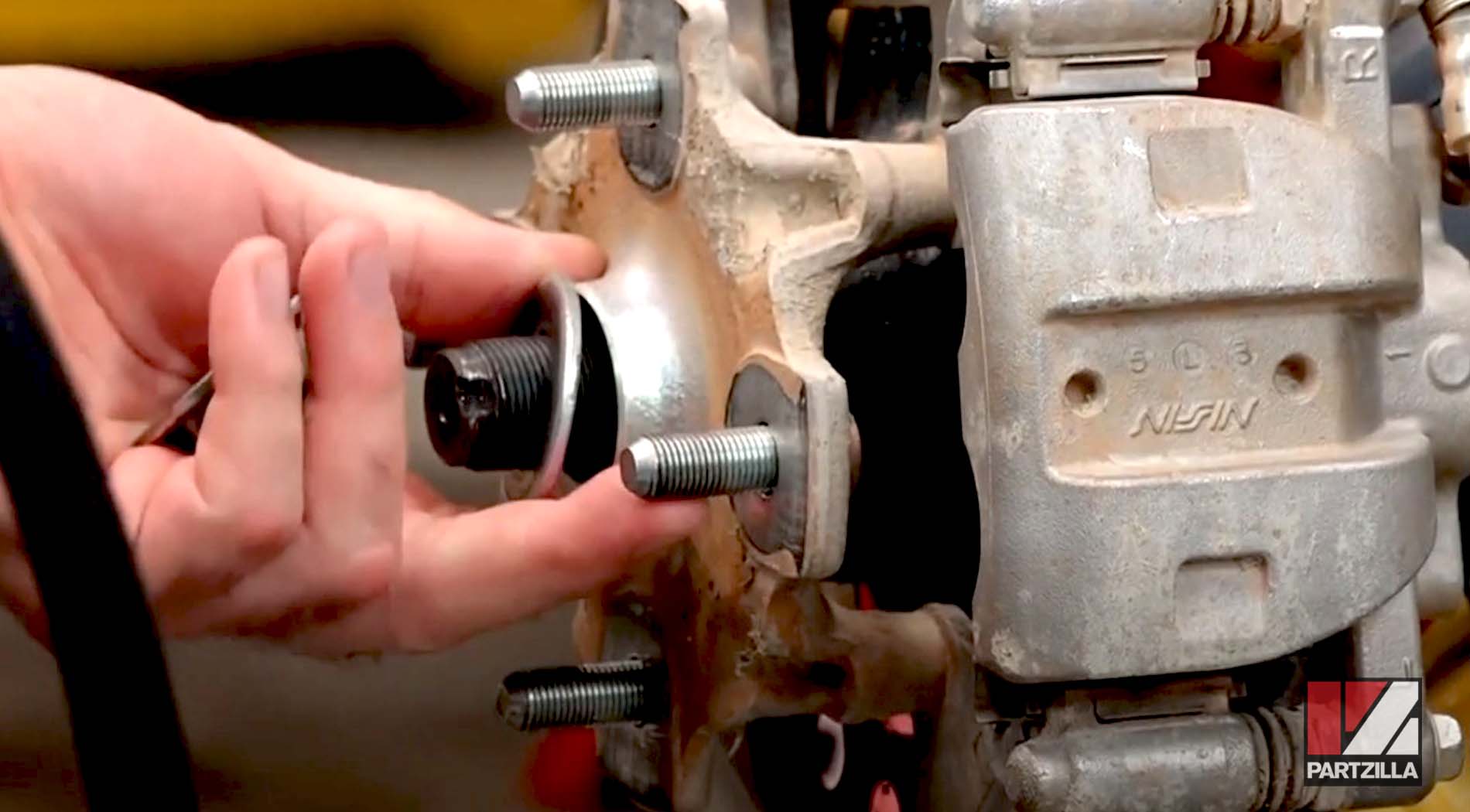
Step 2. Remove the 32mm axle nut and washer.
Step 3. Remove the two 14mm brake caliper mounting bolts and slide the brake caliper assembly off the rotor. Unfasten the brake hose bracket (10mm bolt) from the lower A-arm, and use a zip-tie to hold the caliper assembly out of the way.
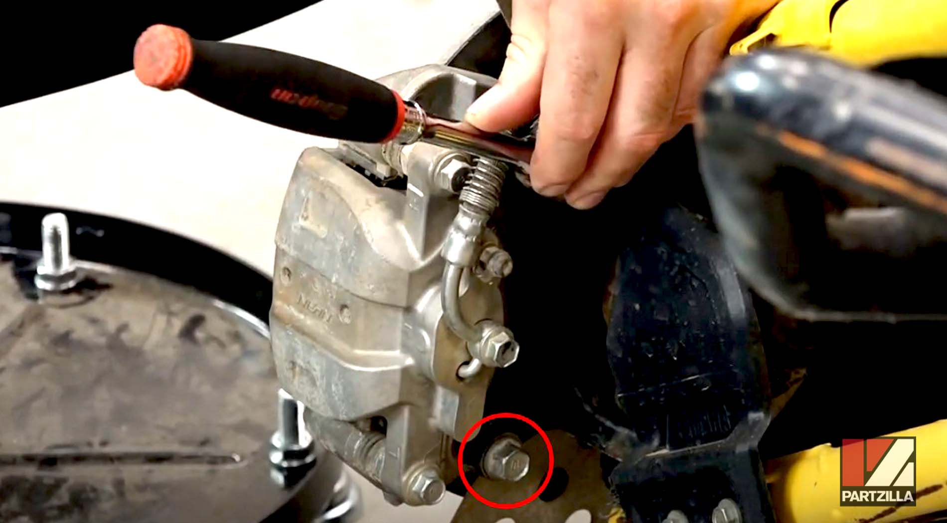
Step 4. Slide the wheel hub out from the steering knuckle assembly, then remove the cotter pin from the 19mm castle nut holding the steering joint, followed by the castle nut and washer.
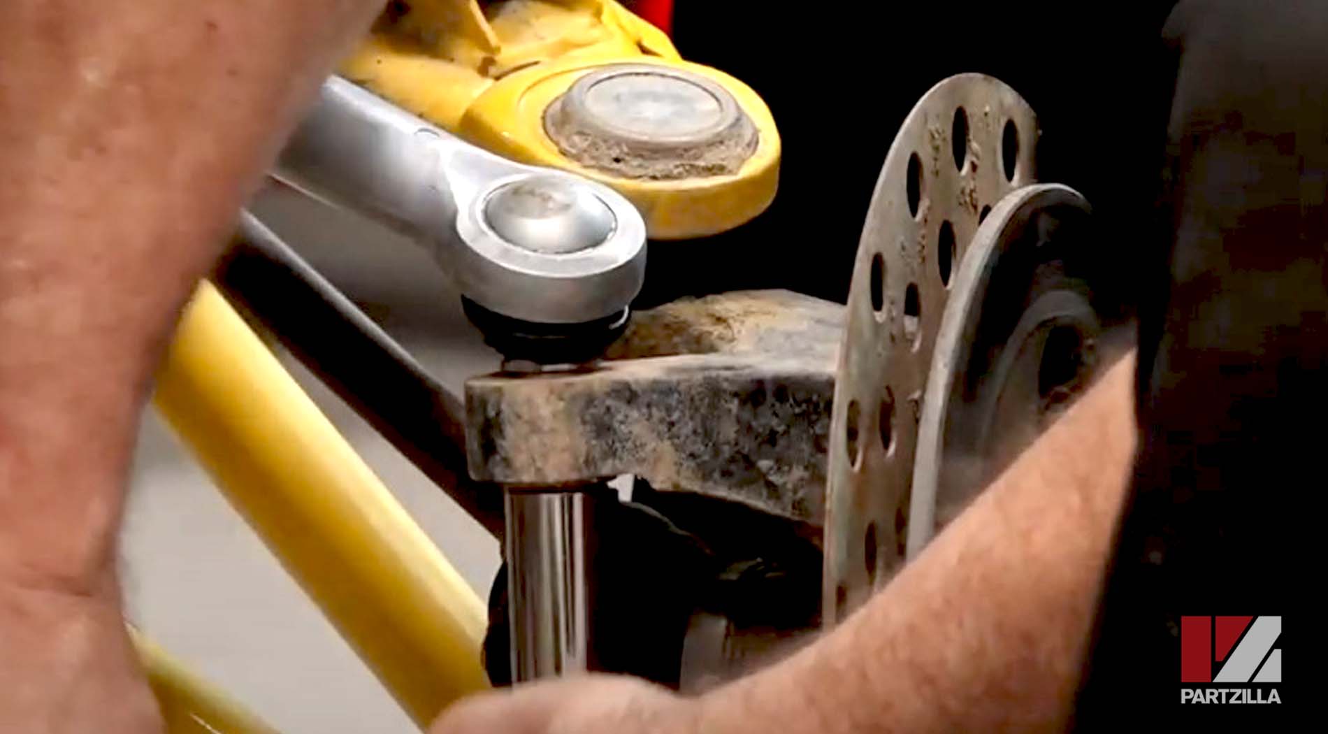
Step 5. Remove the steering joint from the steering knuckle assembly. Use a soft-blow hammer to knock it out if necessary.
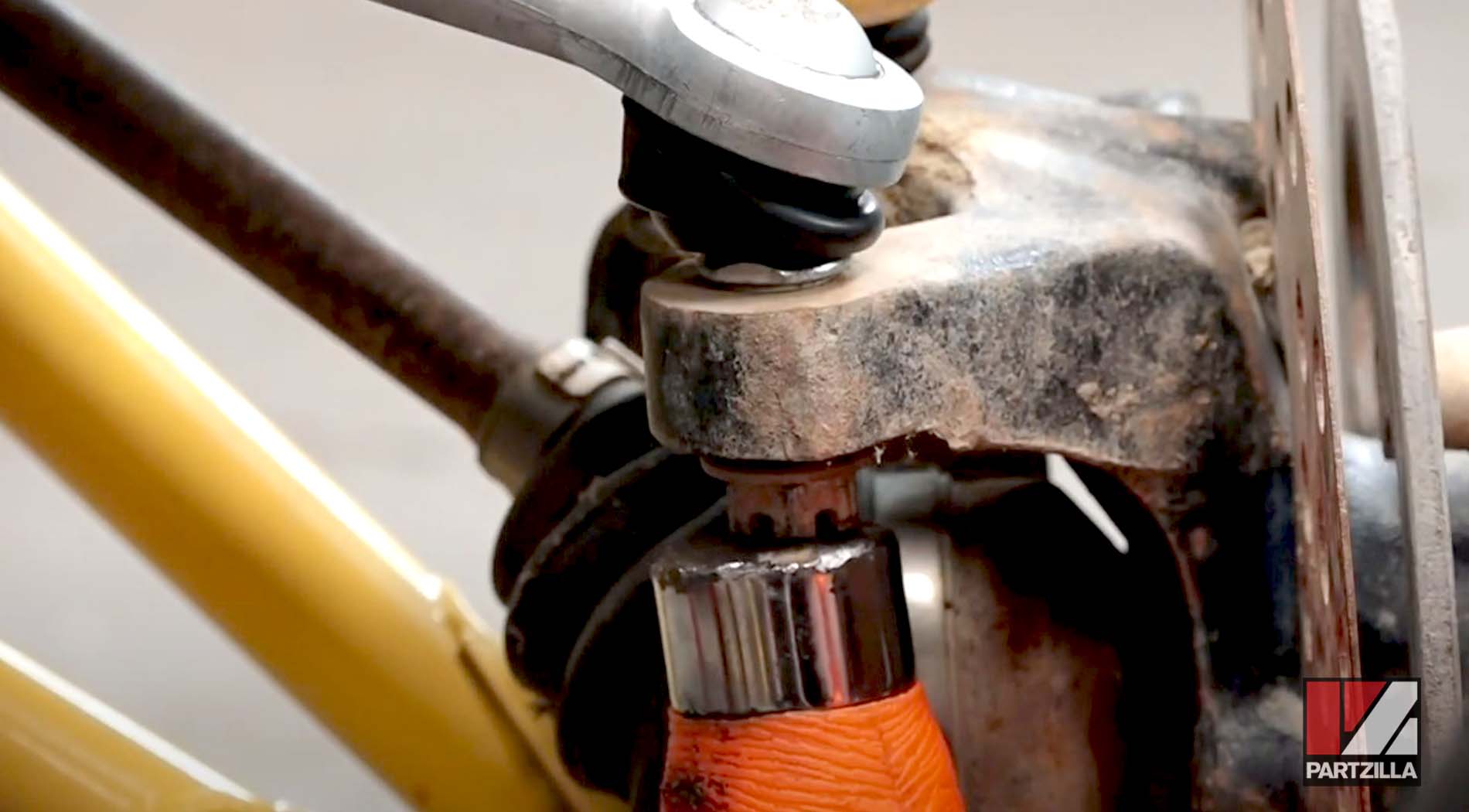
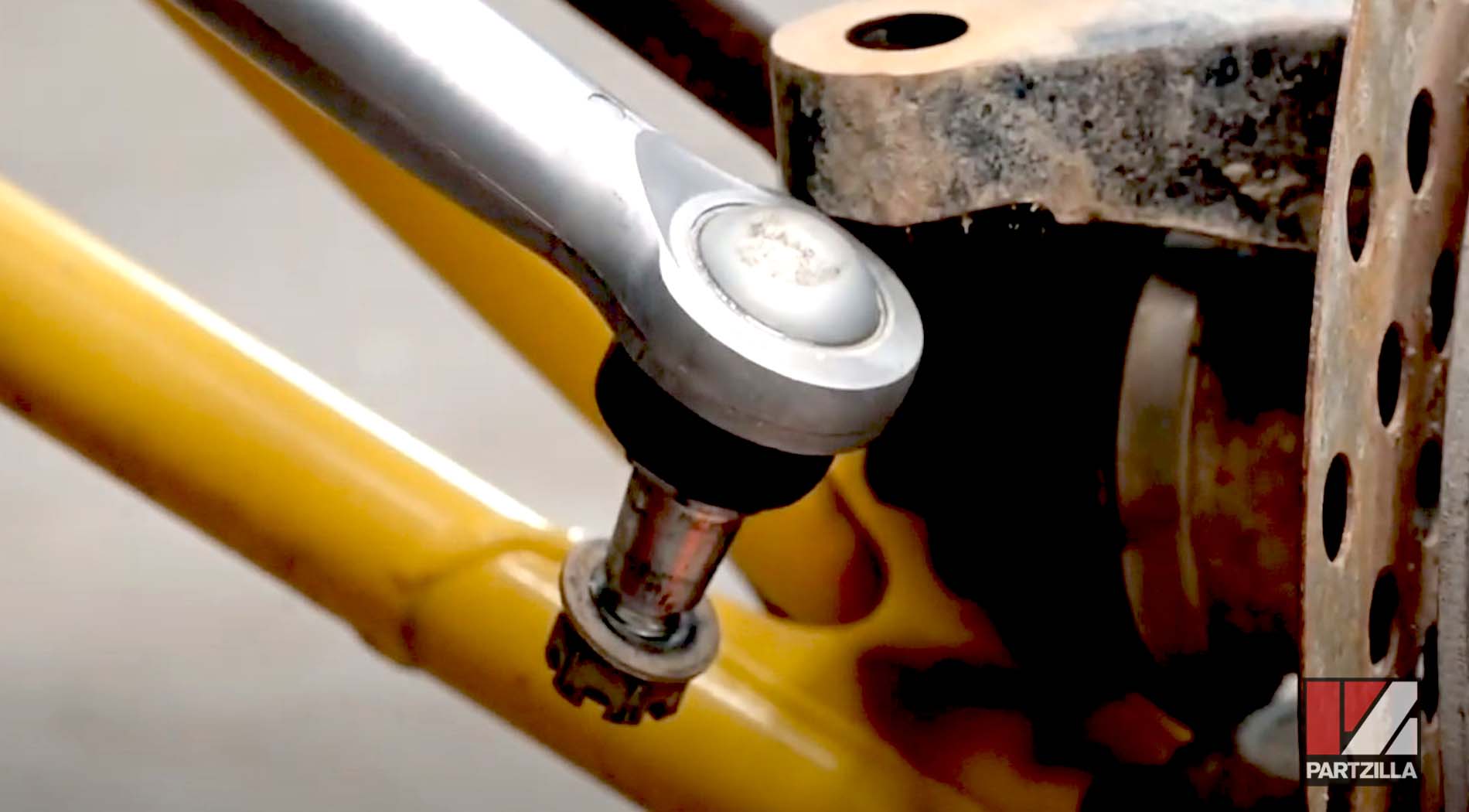
Step 6. Remove the shock absorber mounting bolt (14mm bolt, 17mm nut) and slide the shock absorber from the upper A-arm. Use a bungee cord to hold the shock absorber out of the way.
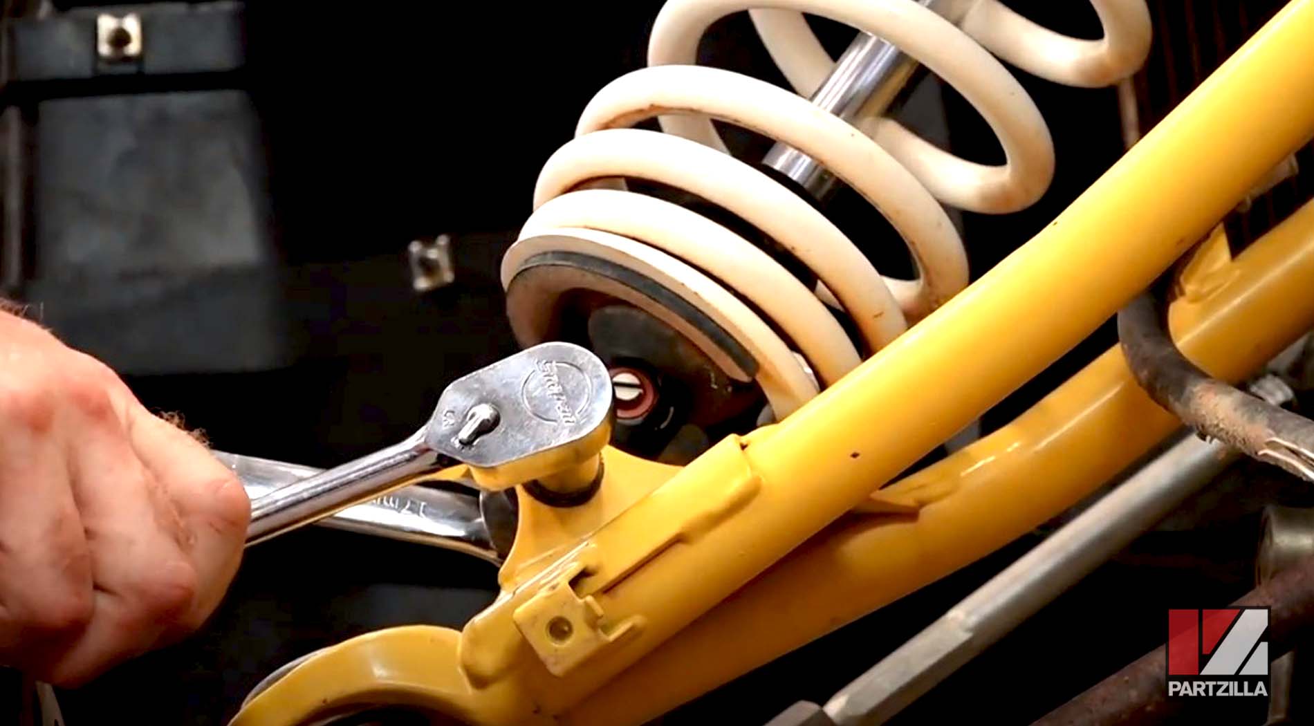
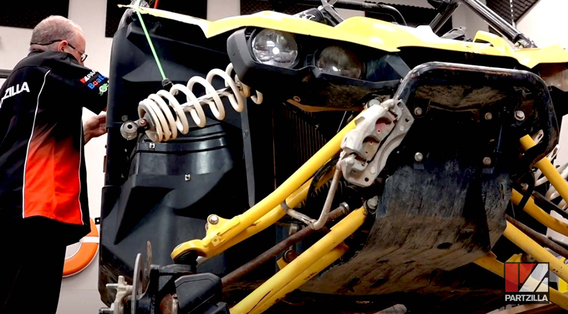
Step 7. Remove the cotter pin from the 22mm castle nut holding the lower ball joint, followed by the castle nut itself.
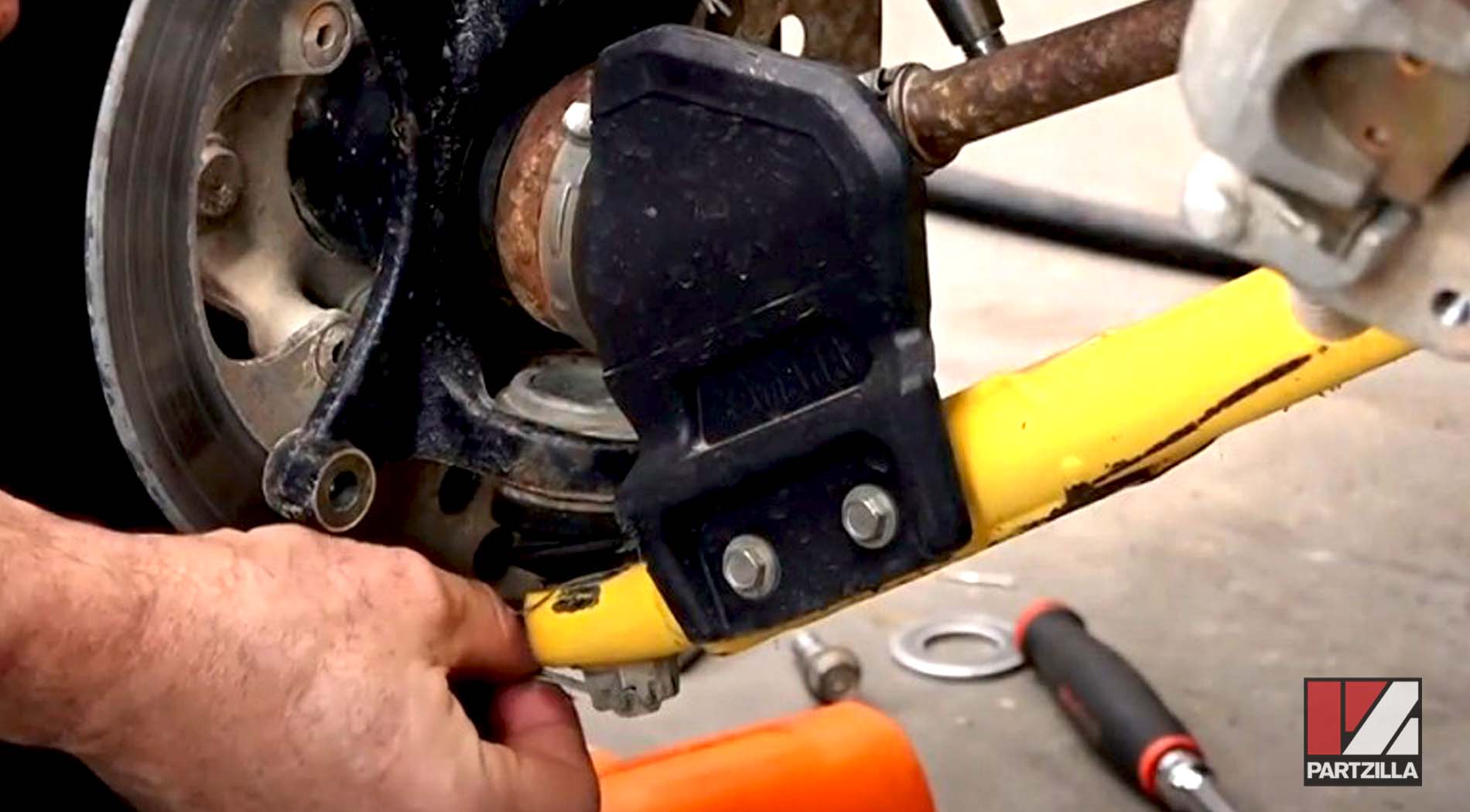
Step 8. Thread a disposable 22mm nut onto the lower ball joint to protect it, then knock the ball joint free from the lower A-arm with a hammer.
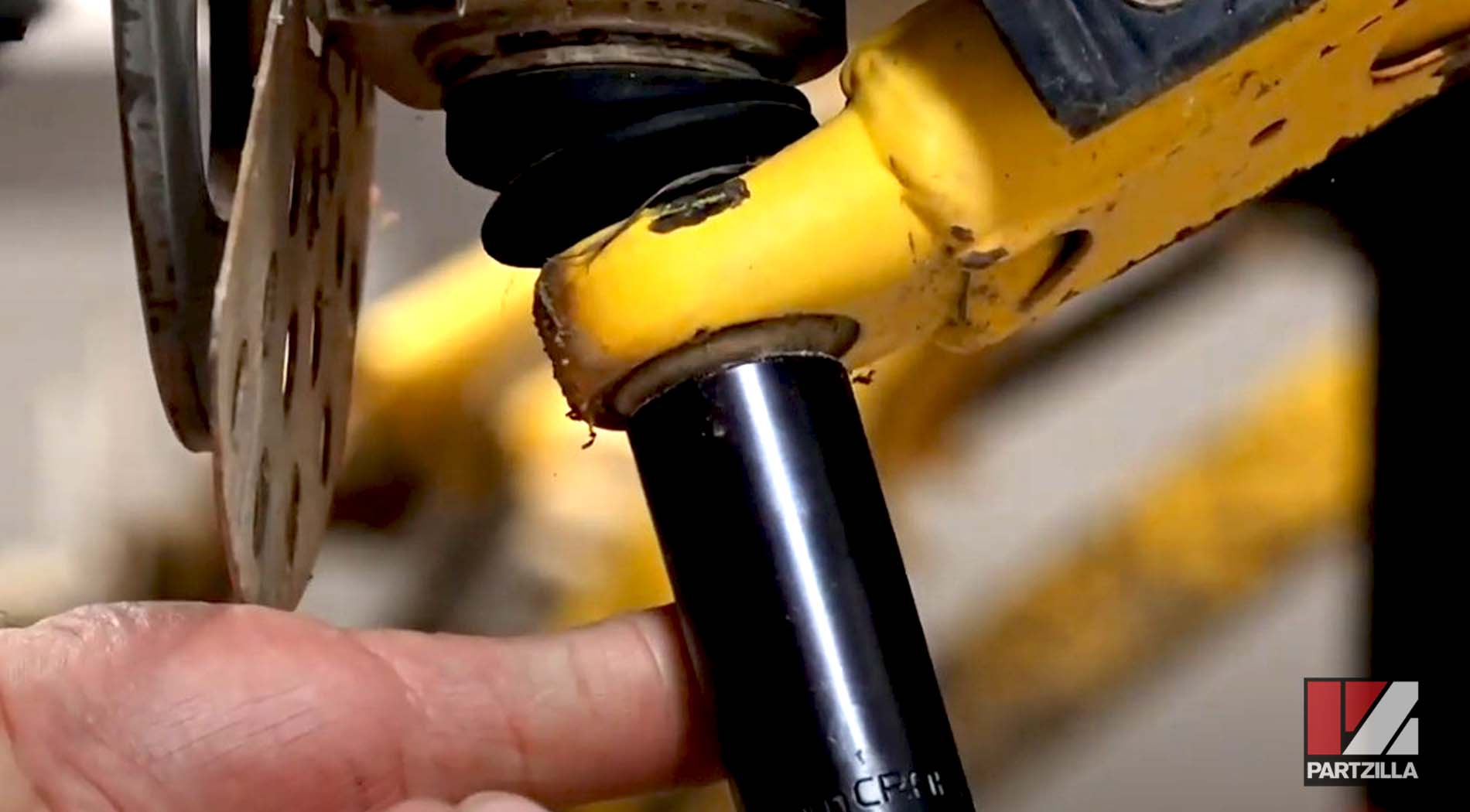
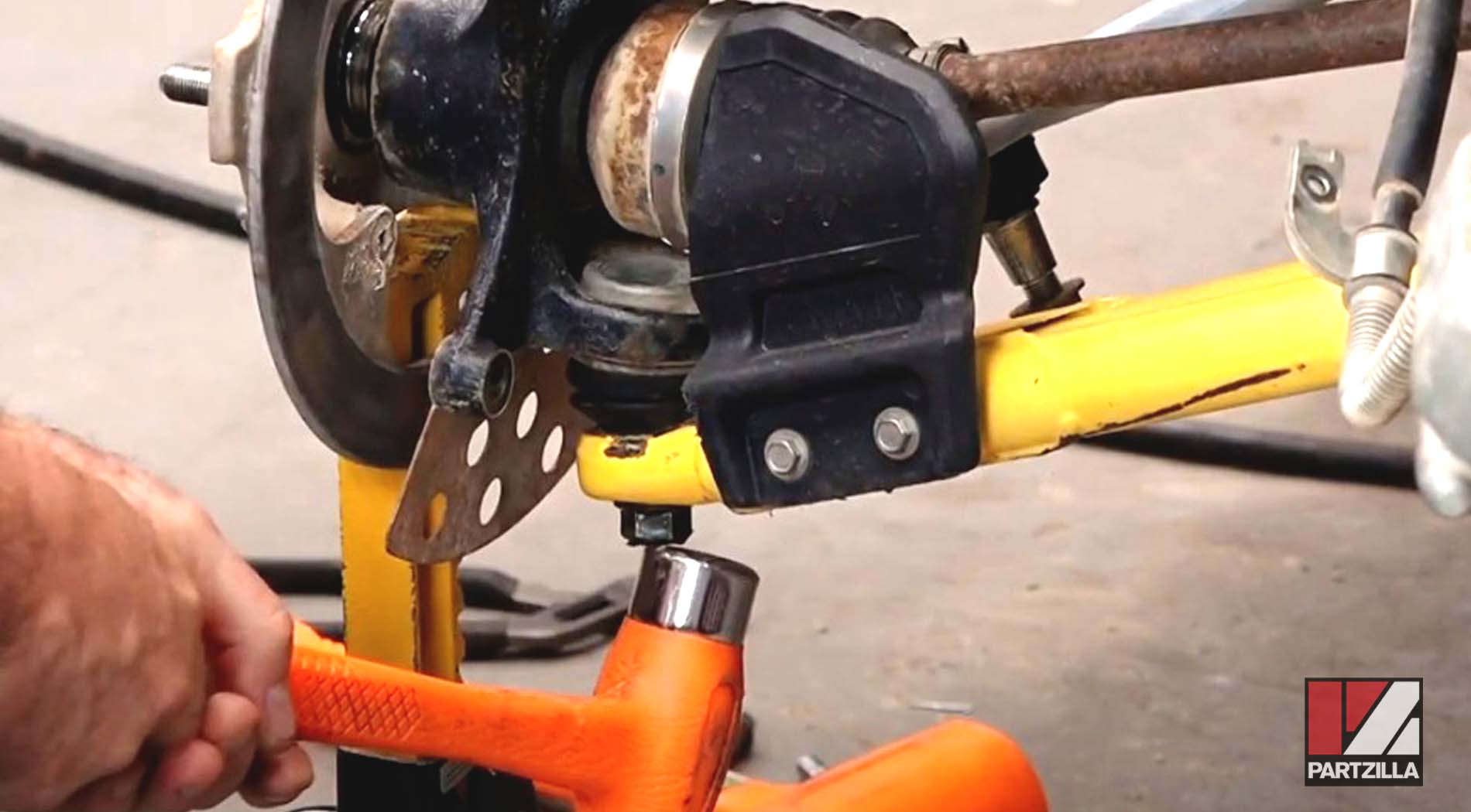
Step 9. Slide the CV joint out from the steering knuckle assembly.
Step 10. Remove the cotter pin from the 22mm castle nut holding the upper ball joint, followed by the castle nut itself.
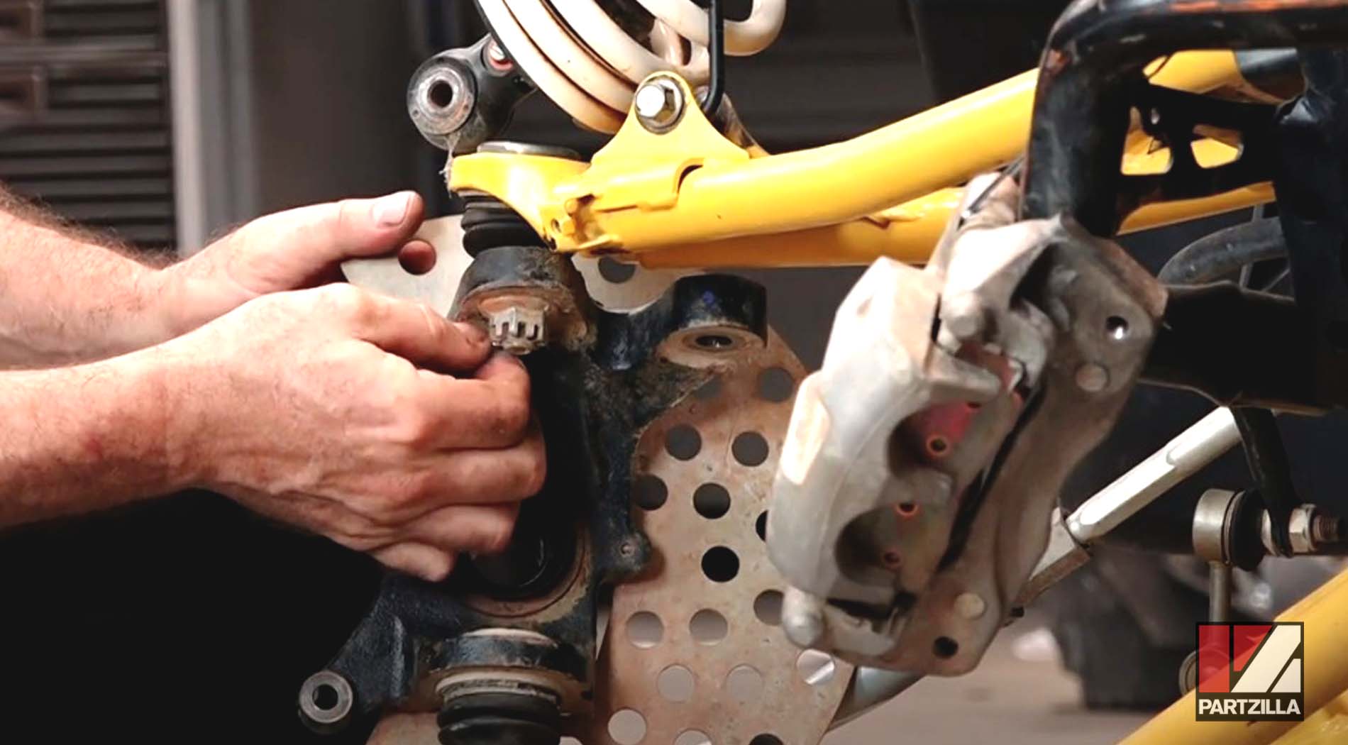
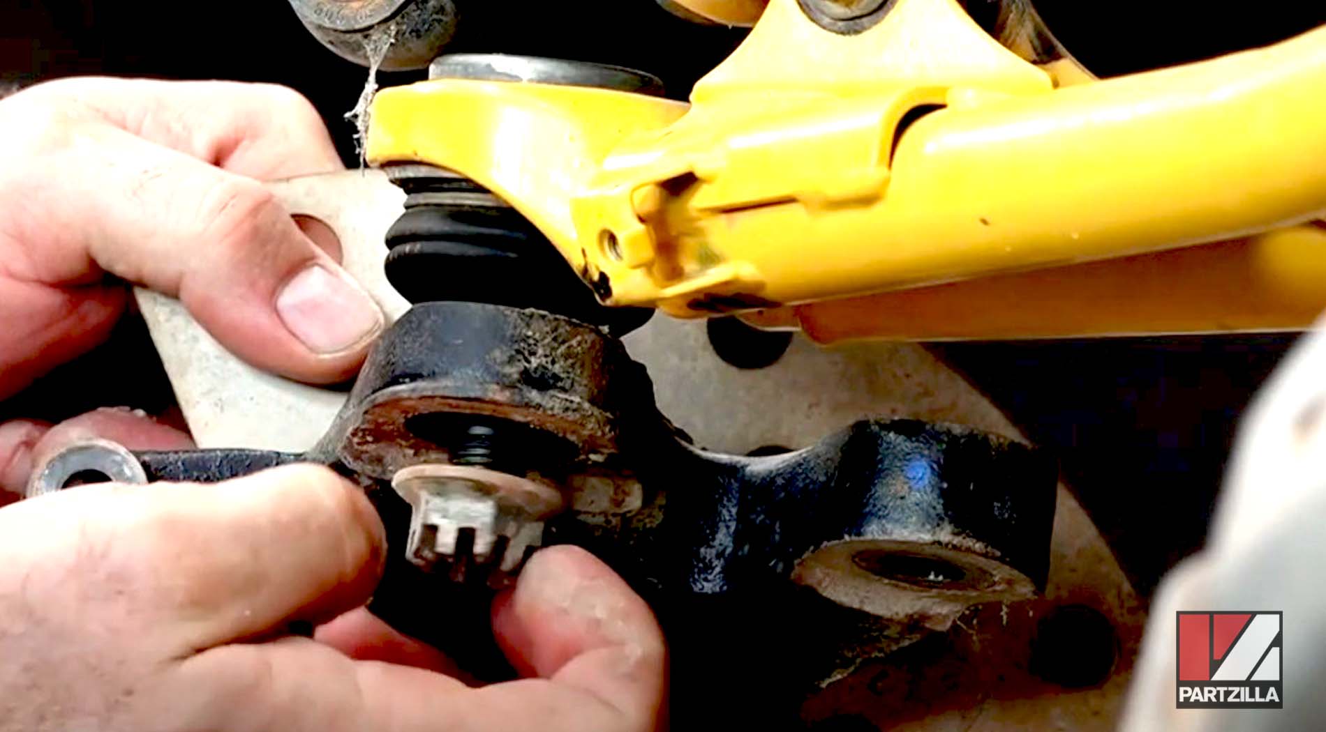
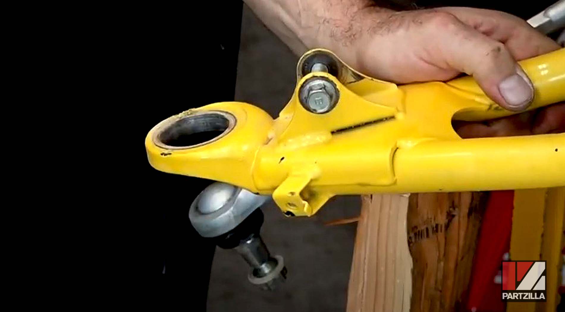
Step 11. Thread a disposable 22mm nut onto the upper ball joint to protect it, then knock the ball joint free from the upper A-arm with a soft blow hammer and remove the steering knuckle.
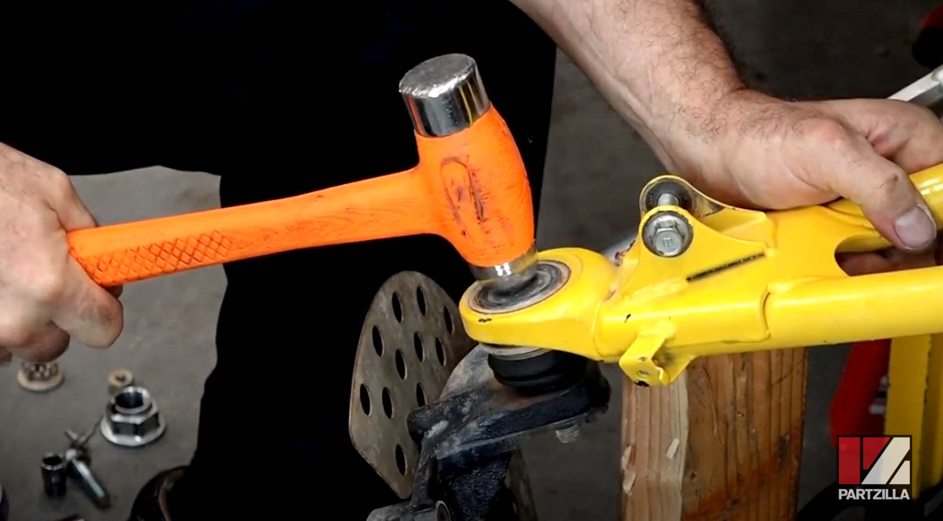
Step 12. Remove the three 4mm bolts and the wheel guard from the steering knuckle.
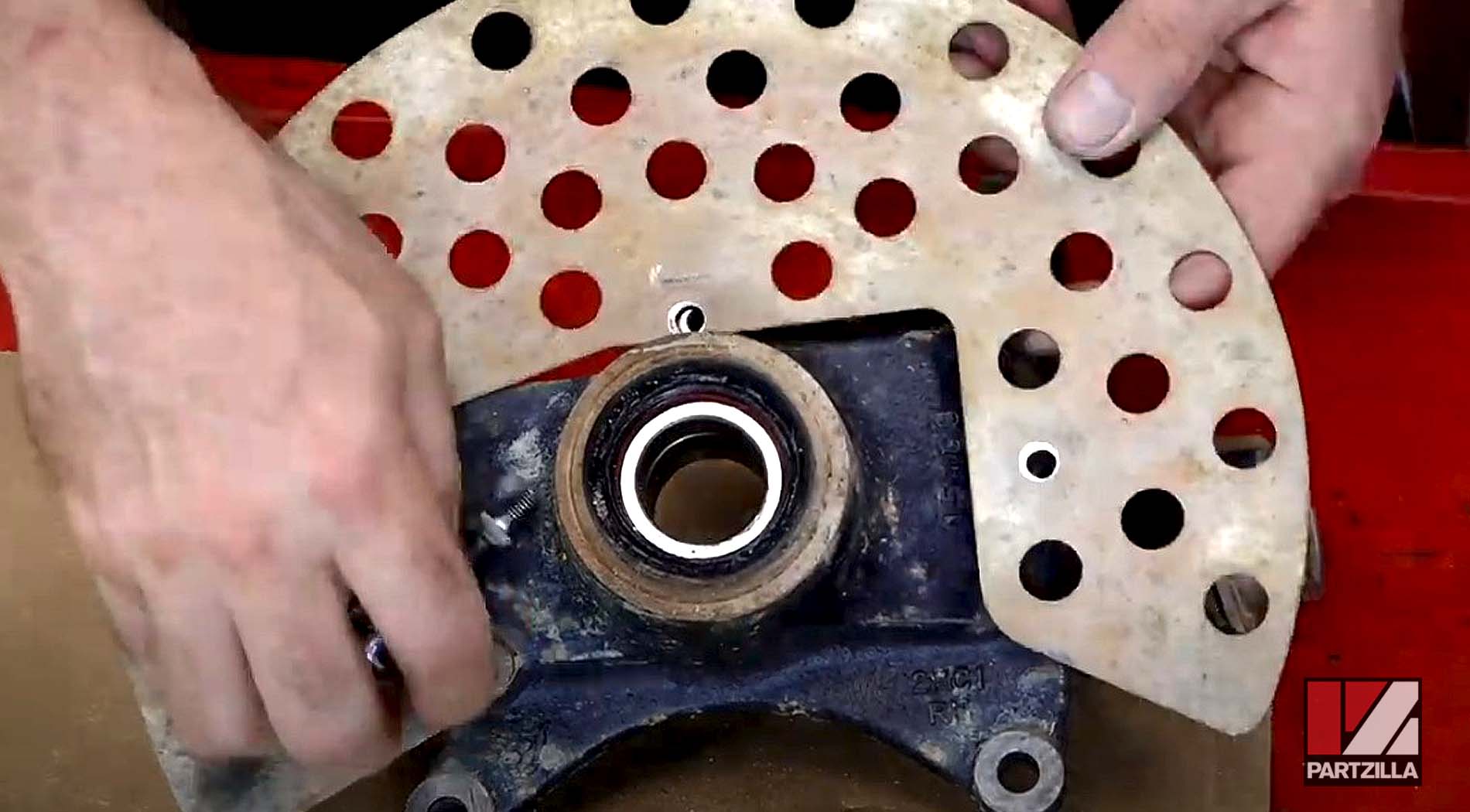
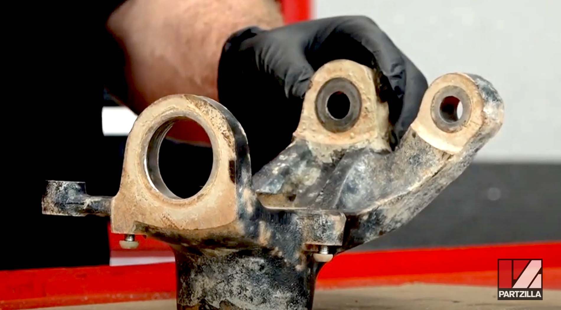
Watch the clip below to see the steering knuckle disassembly segment of our Yamaha YXZ1000R wheel bearings video.
Removing Yamaha YXZ1000R Wheel Bearings
Step 13. Remove the two oil seals from the steering knuckle with a flat-blade screwdriver.
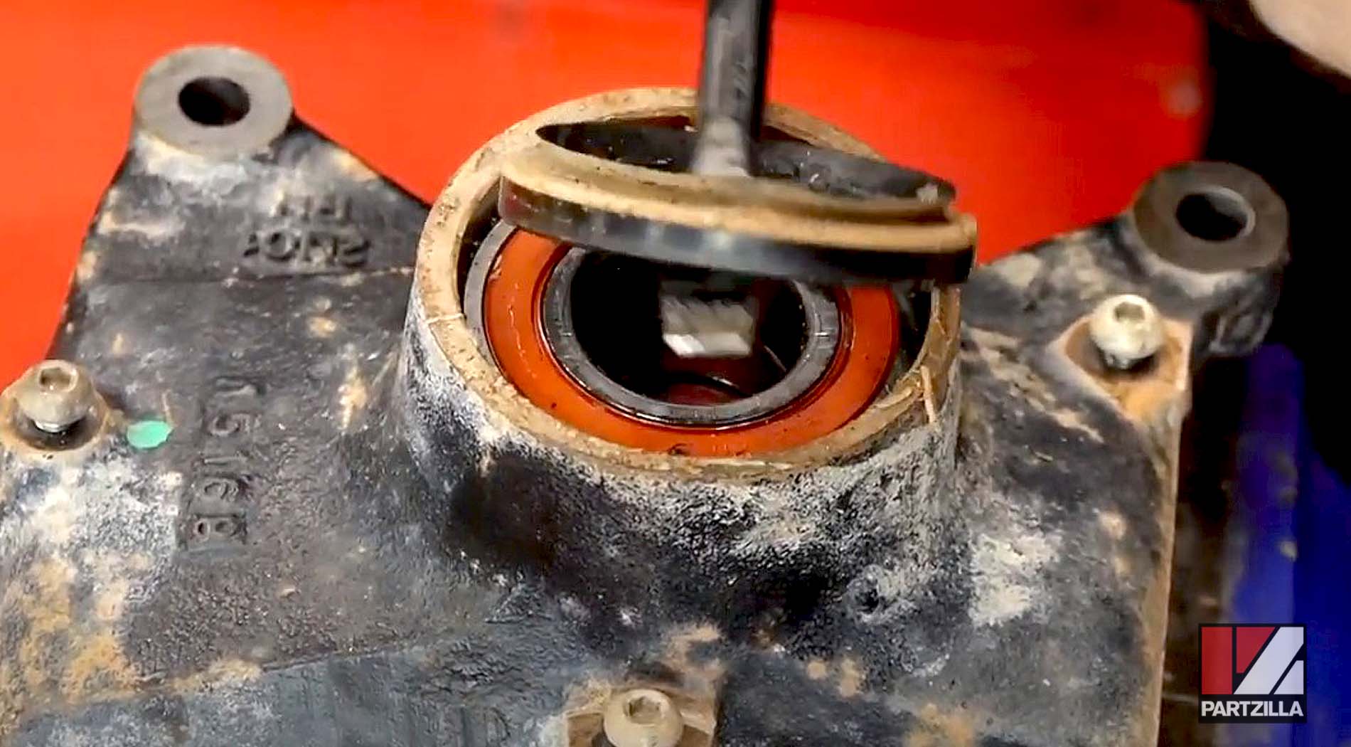
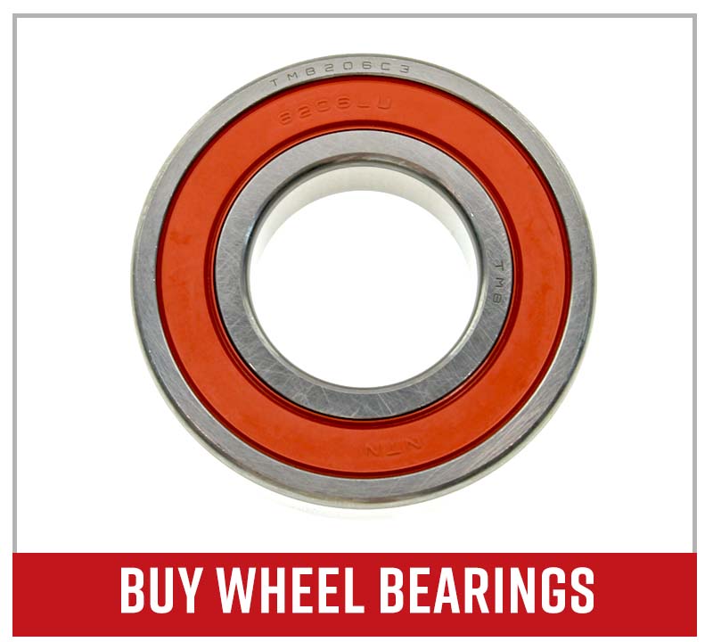
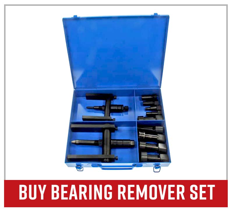
Step 14. Remove the inner and outer wheel bearings from the steering knuckle with a bearing remover.
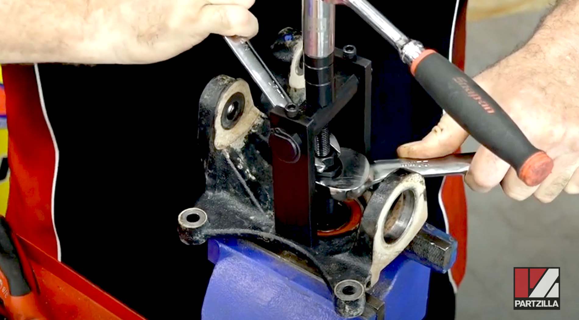
NOTE: Don’t lose the metal collar between the oil seals.
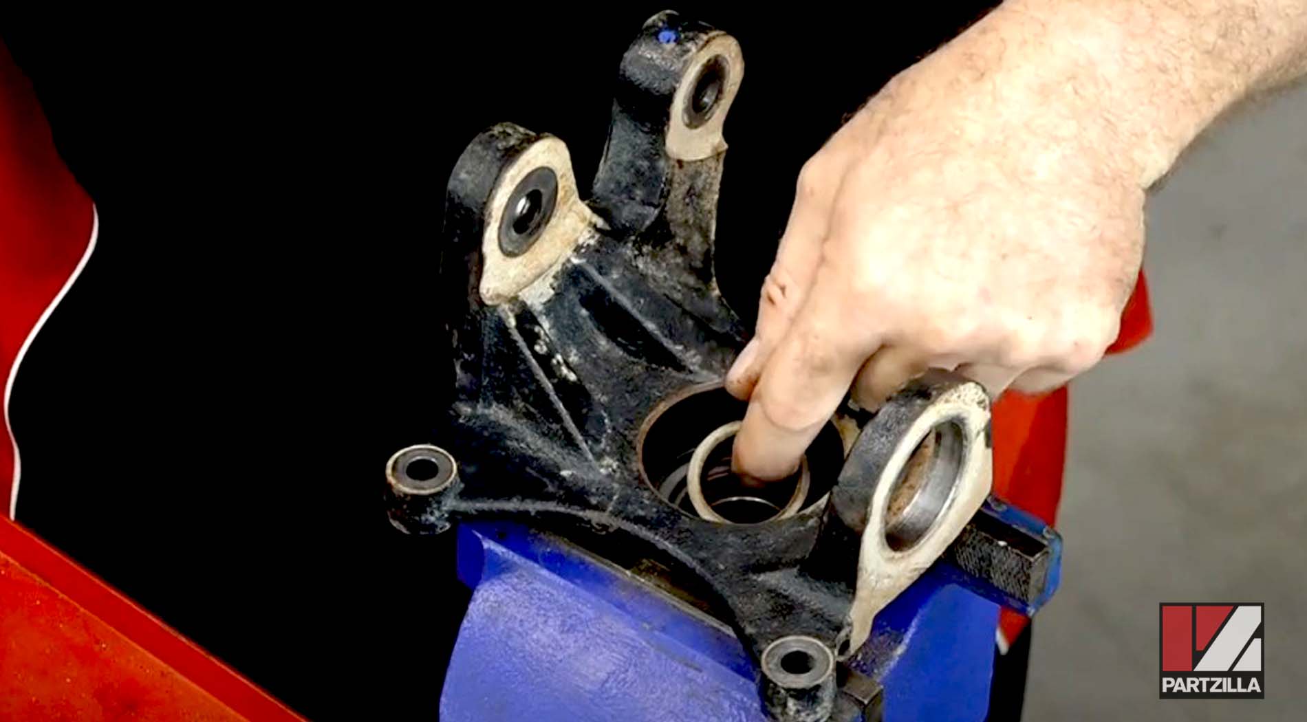
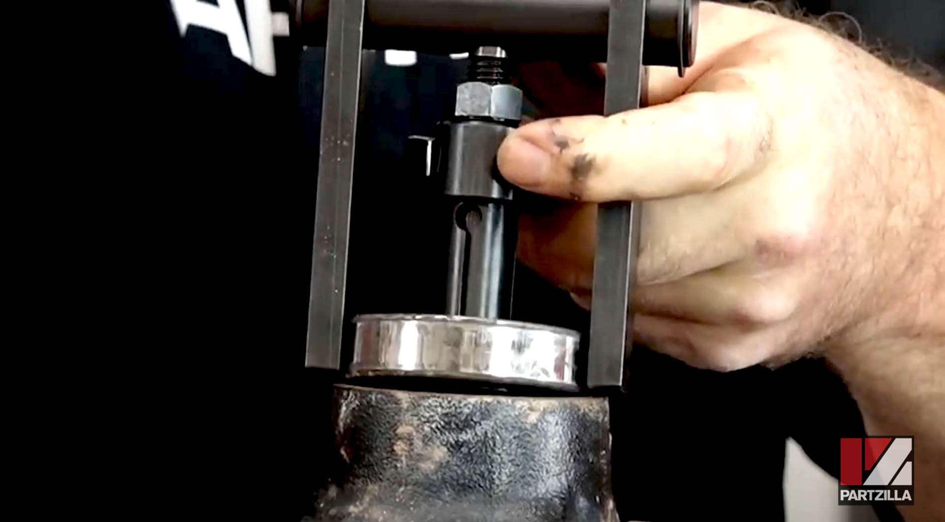
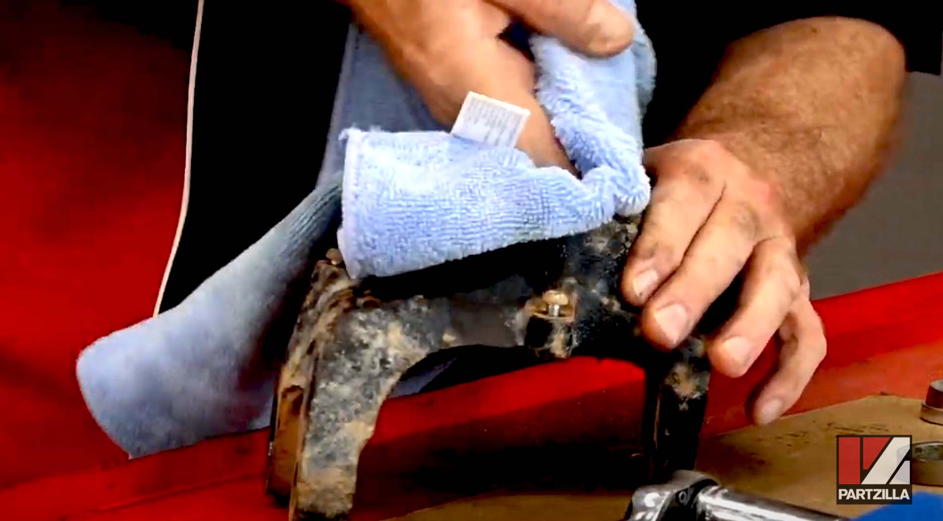
Step 15. Clean the steering knuckle with contact/brake cleaner.
Watch the clip below to see the wheel bearing removal segment of our Yamaha YXZ1000R wheel bearings video.
Installing Yamaha YXZ1000R Wheel Bearings
Step 16. Install the new outer wheel bearing into the steering knuckle using a bearing driver with a diameter that contacts the outer edge of the bearing. Press the new bearing into the steering knuckle until it bottoms out.
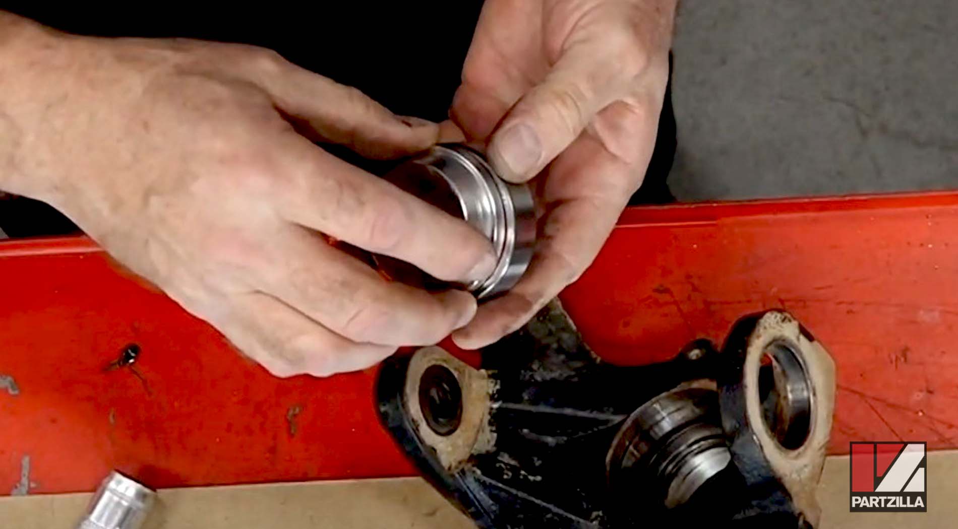
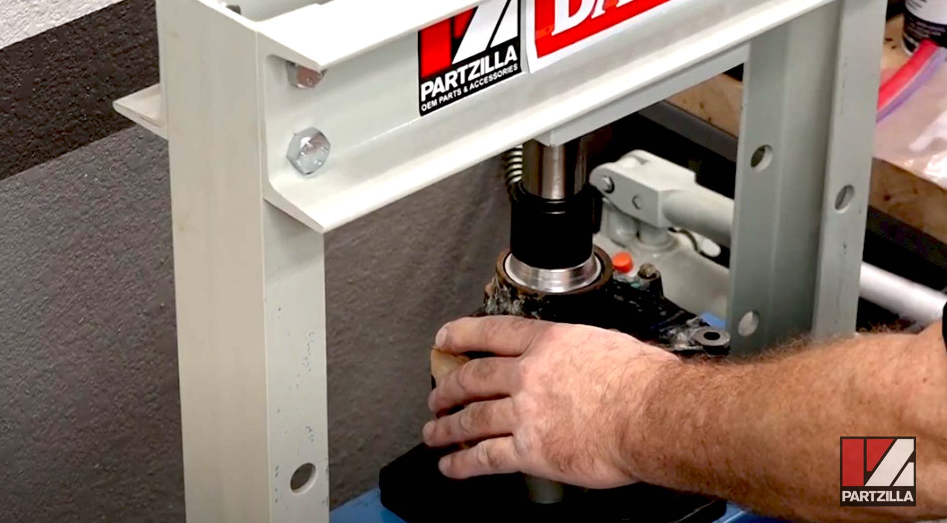
Step 17. Reinstall the metal collar.
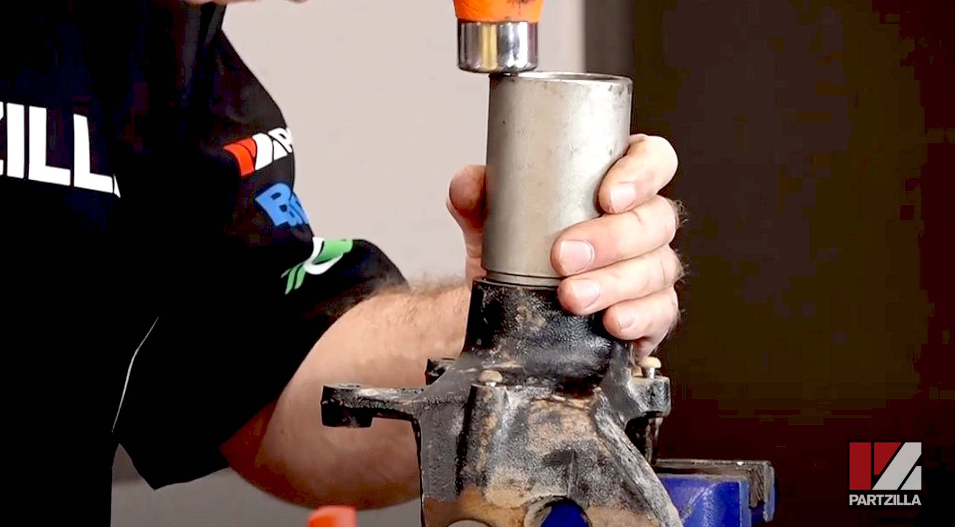
Step 18. Install the new inner wheel bearing into the steering knuckle using a bearing driver with a diameter that contacts the outer edge of the bearing. Press the new bearing into the steering knuckle until it bottoms out.
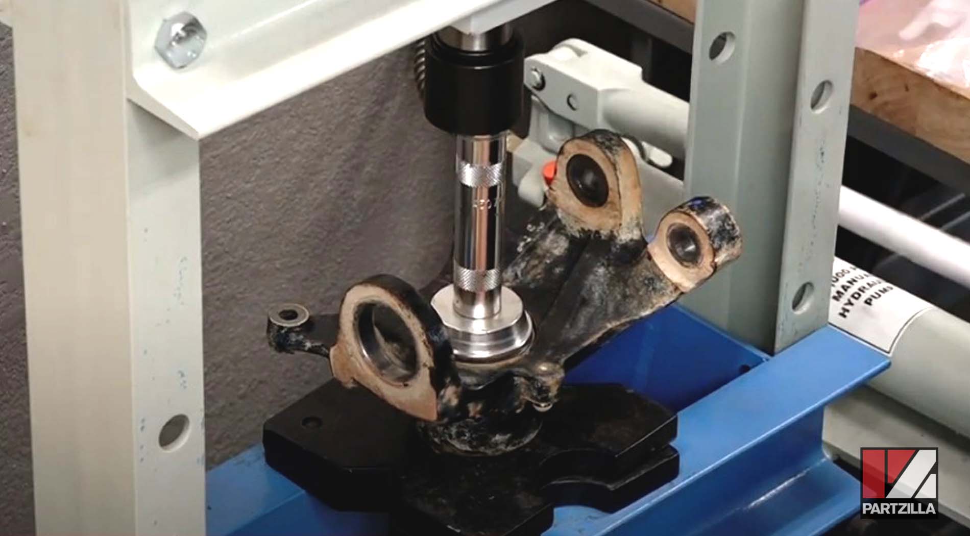
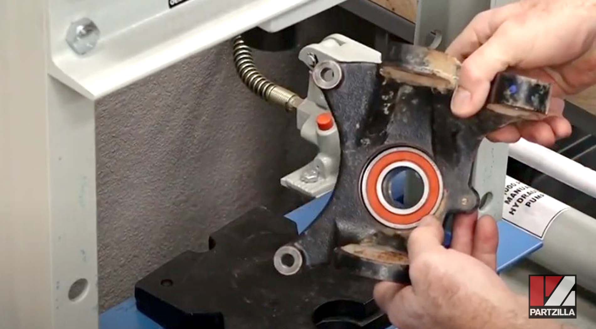
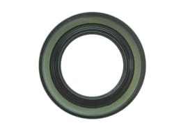
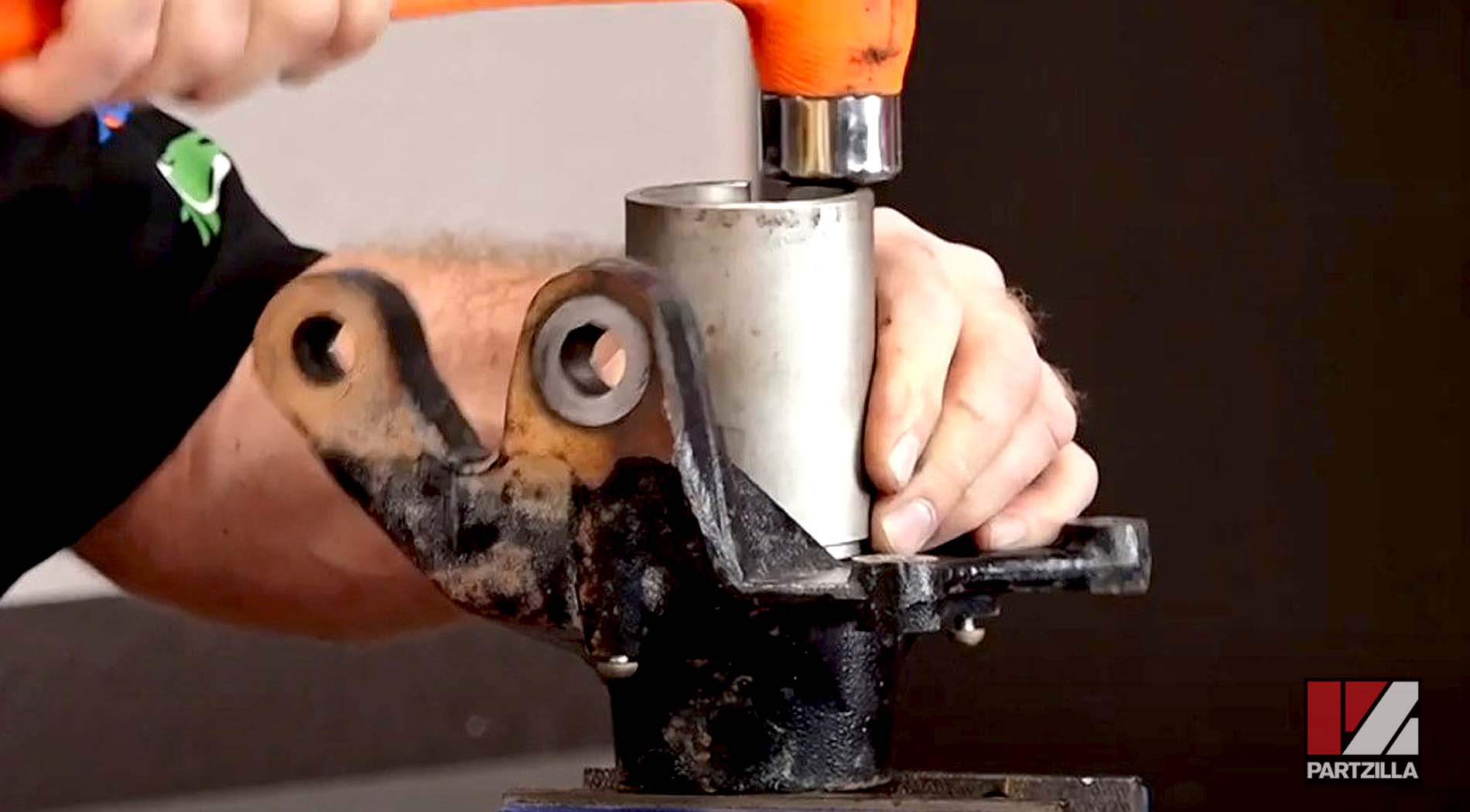
Step 19. Install the new inner and outer oil seals into the steering knuckle using a collar with a diameter that contacts the outer edge of the oil seal. Drive the new oil seals down until they're flush with the steering knuckle.
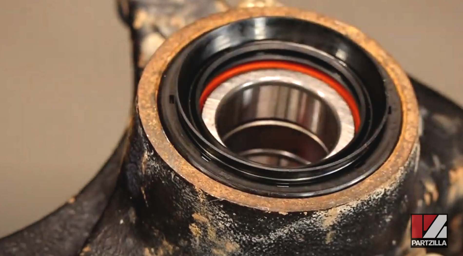
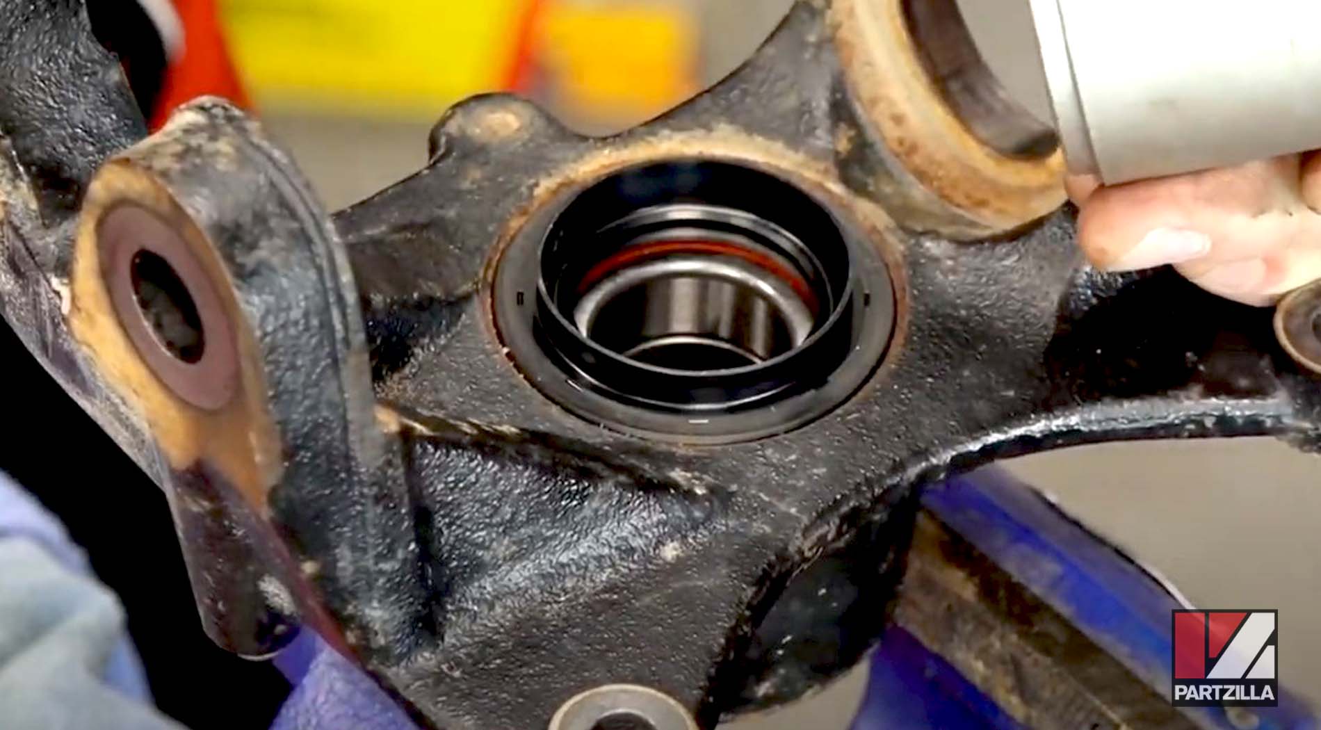
Step 20. Pack the inner edges of the new oil seals with grease.
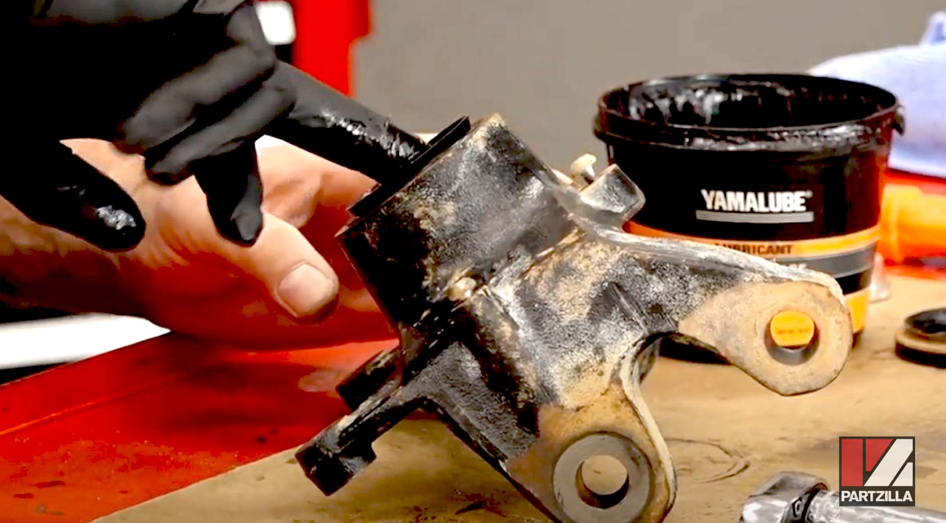
Watch the clip below to see the wheel bearing installation segment of our Yamaha YXZ1000R wheel bearings video.
Reinstalling Yamaha YXZ1000R Steering Knuckle Assembly
Step 21. Slide the upper ball joint into the steering knuckle, then reinstall the 22mm castle nut and torque it to 51 foot-pounds. Install a new cotter pin.
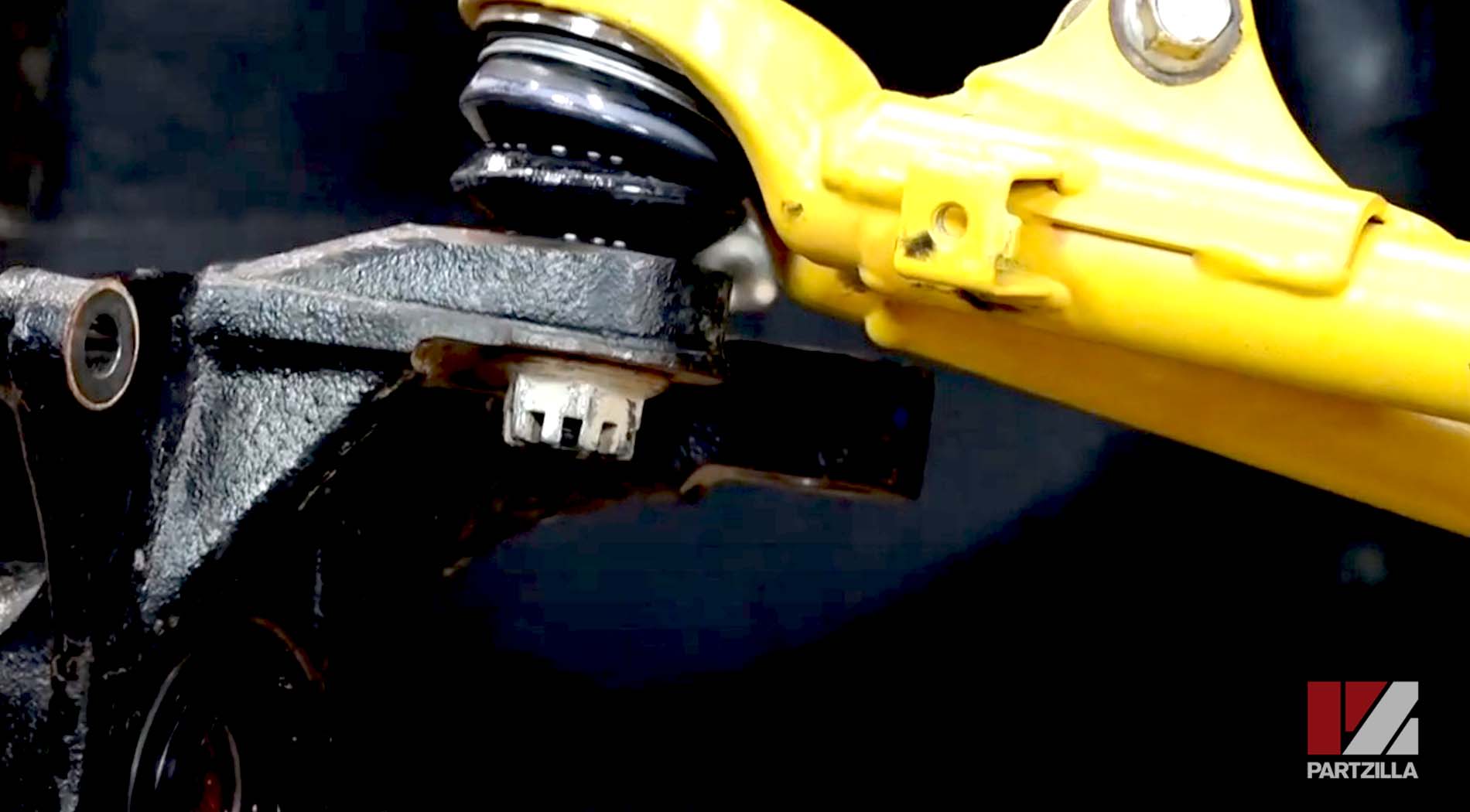
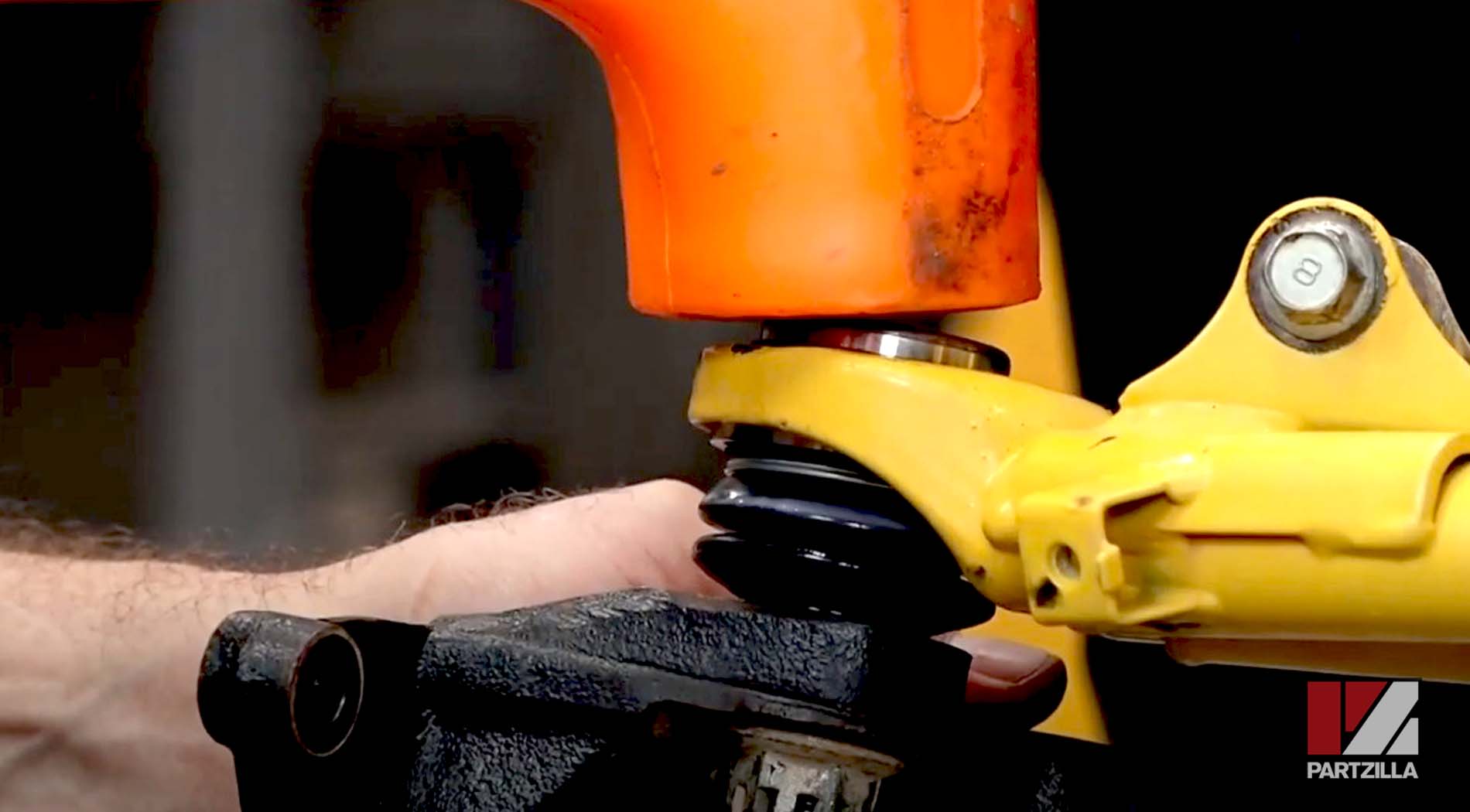
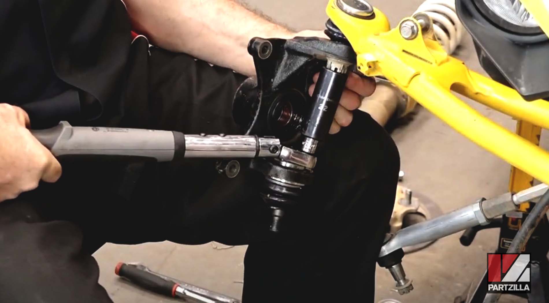
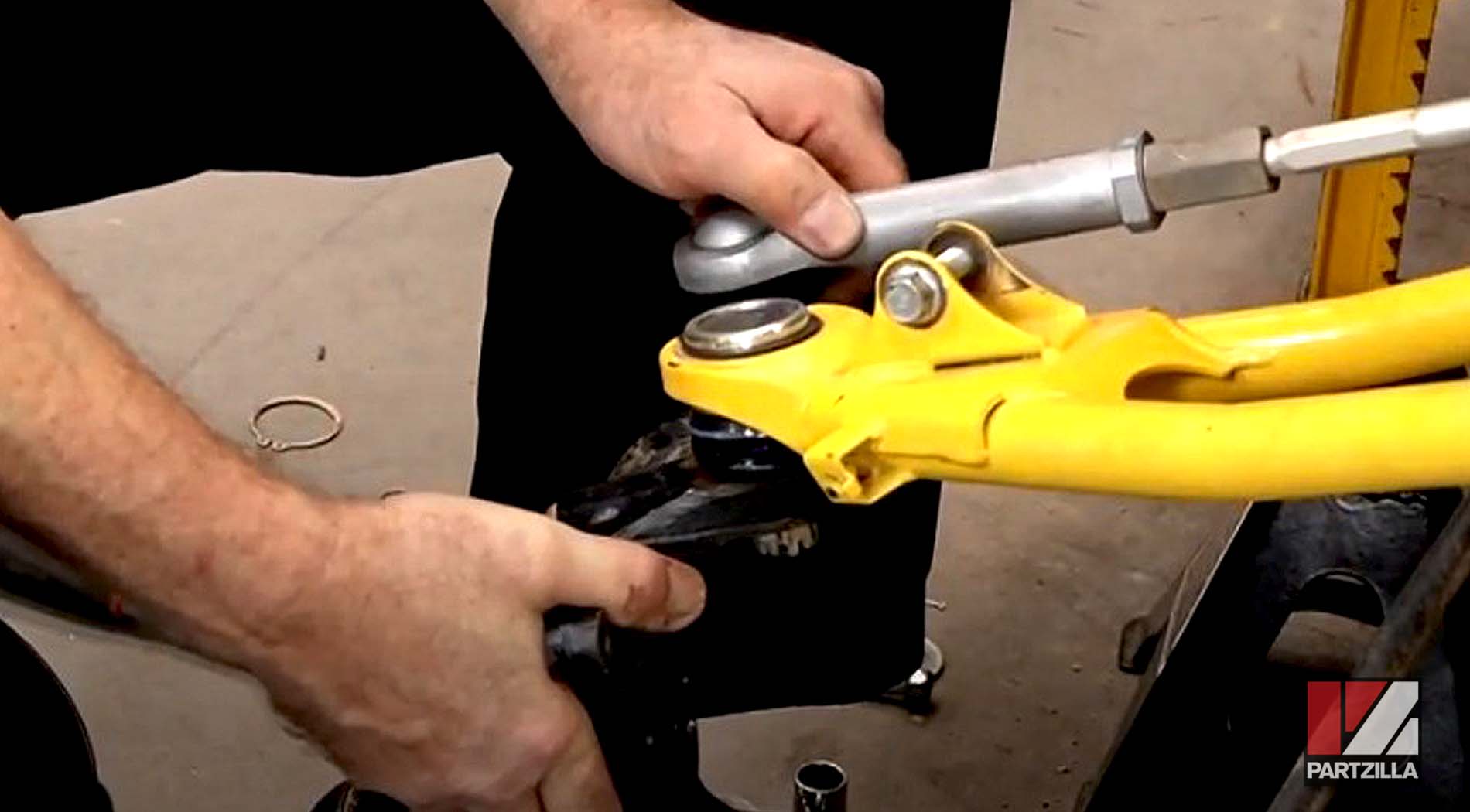
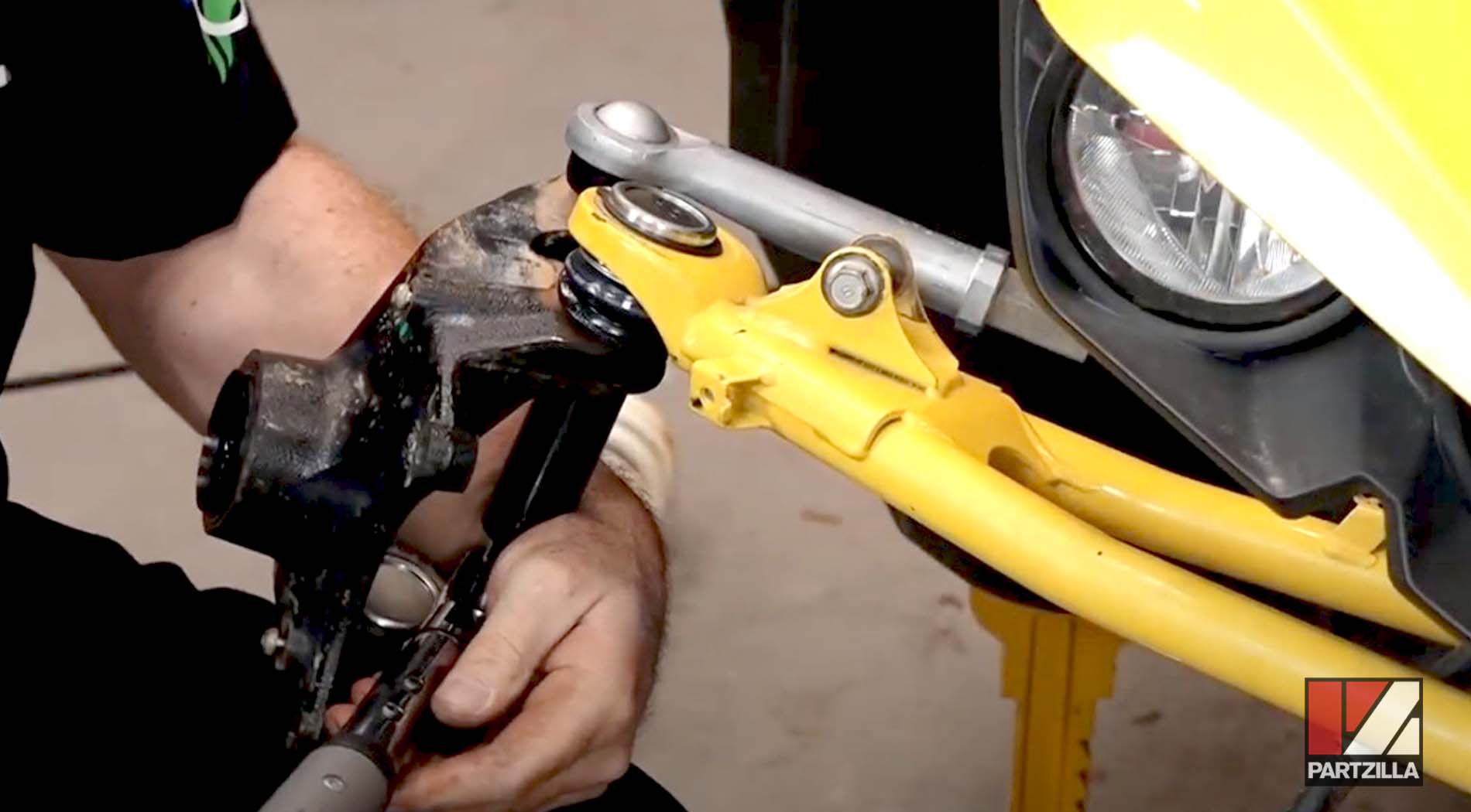
Step 22. Refasten the brake hose bracket (10mm bolt) to the upper A-arm.
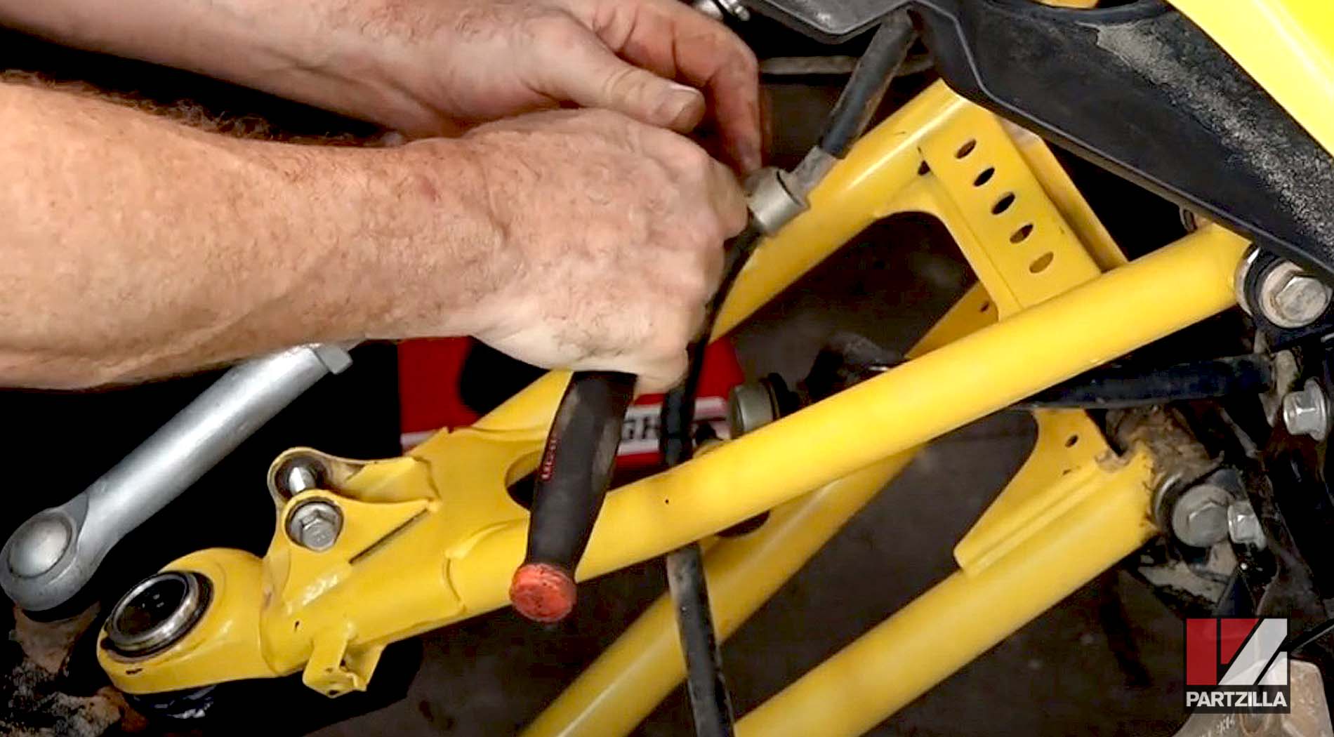
PRO TIP: If you removed the driveshaft earlier, reinstall it now by tapping it back into the transmission housing.
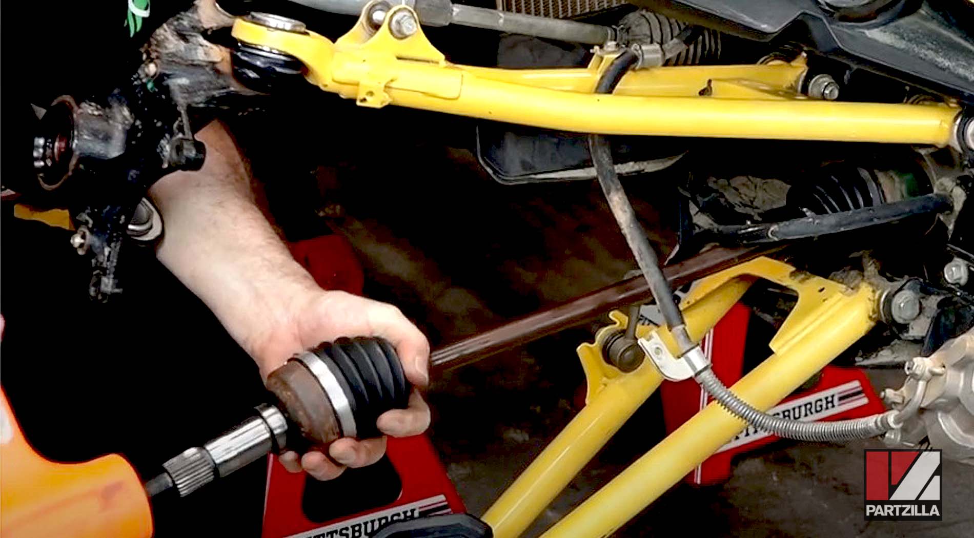
Step 23. Grease the stub axle and axle splines, and slide them back through the steering knuckle.
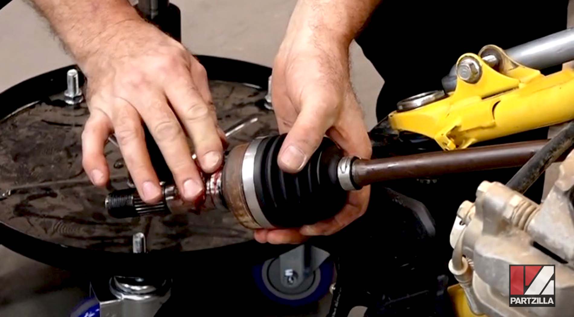
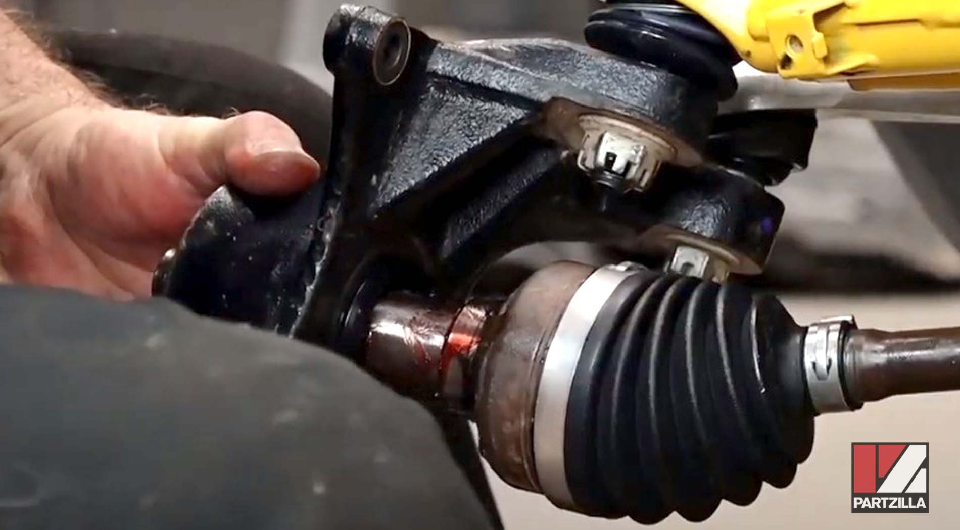
Step 24. Slide the lower ball joint into the lower A-arm, then reinstall the 22mm castle nut and torque it to 51 foot-pounds. Install a new cotter pin.
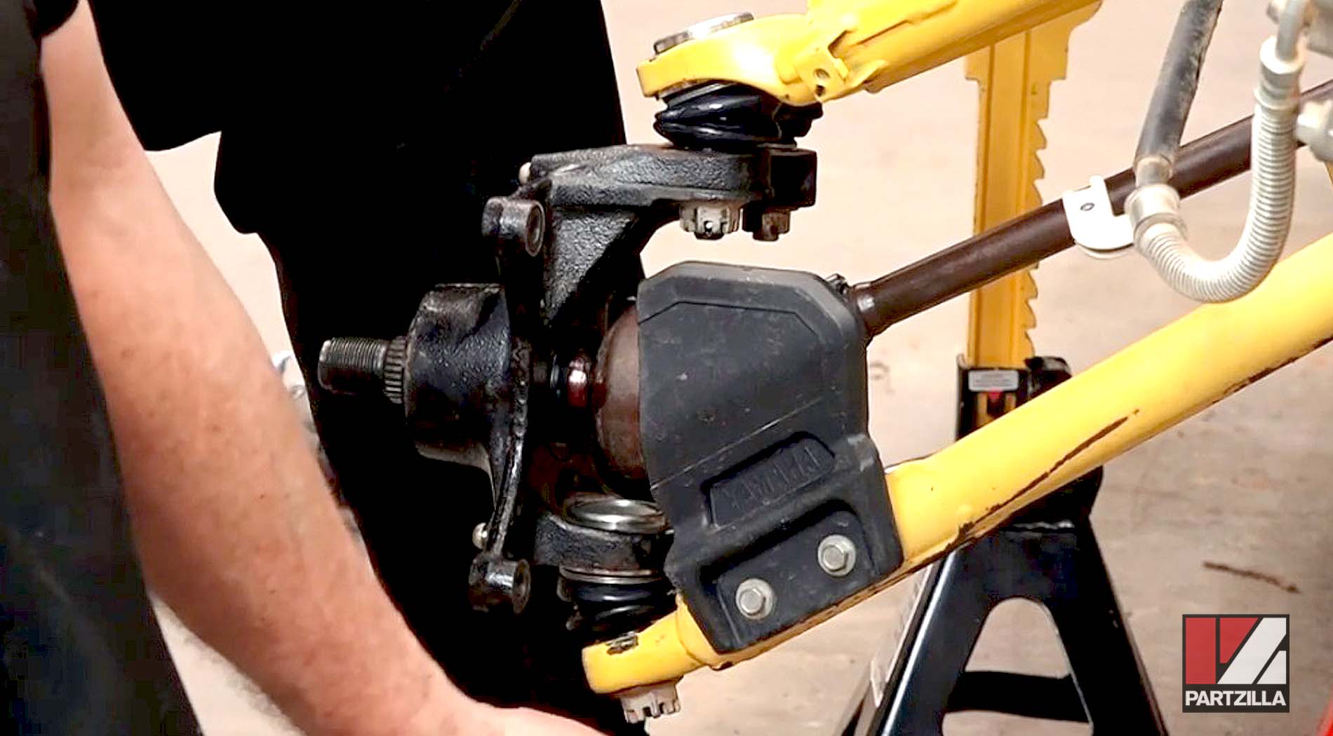
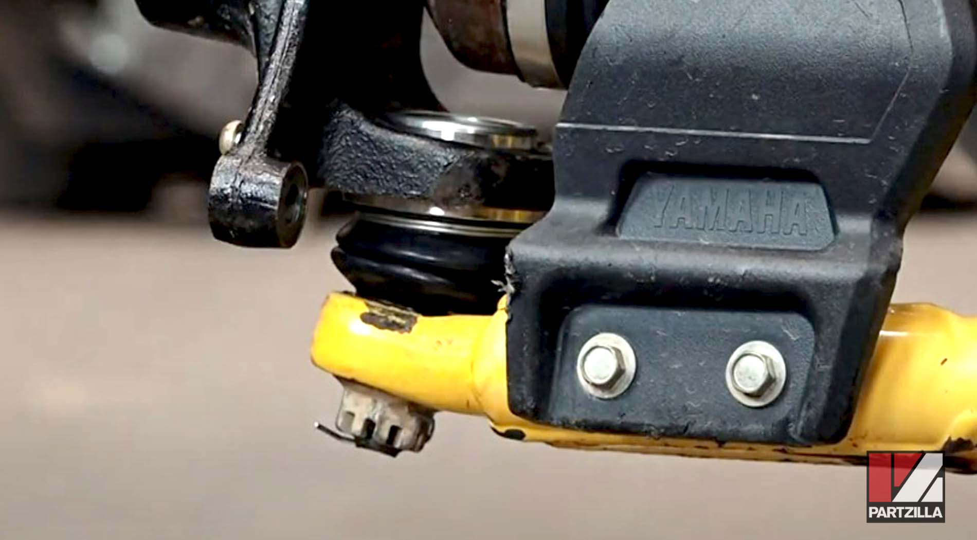
Step 25. Reattach the shock absorber to the upper A-arm, then reinstall the mounting bolt (14mm bolt, 17mm nut).
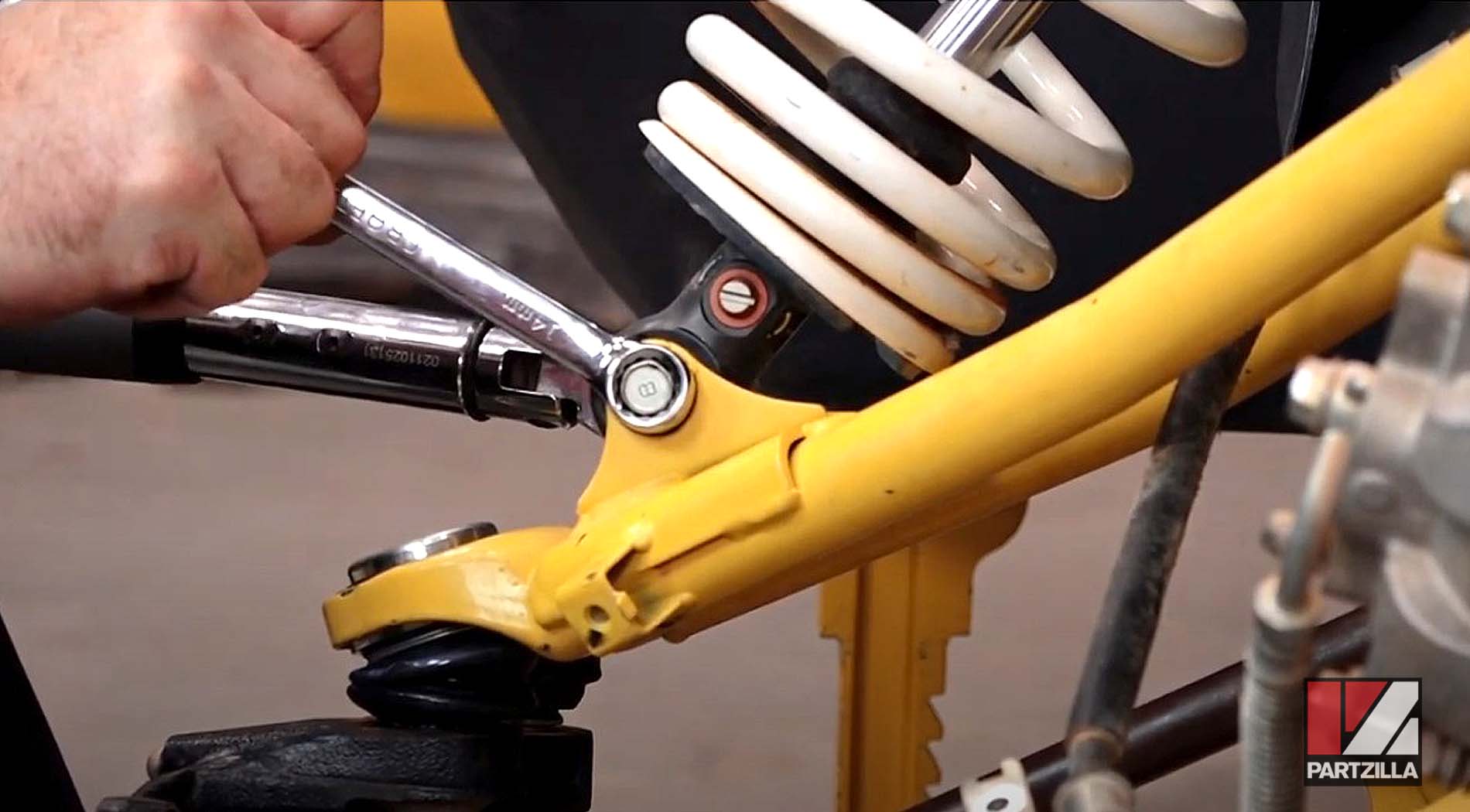
Step 26. Reinstall the steering joint through the steering knuckle assembly, and torque the 19mm castle and washer to 29 foot-pounds. Reinstall the cotter pin.
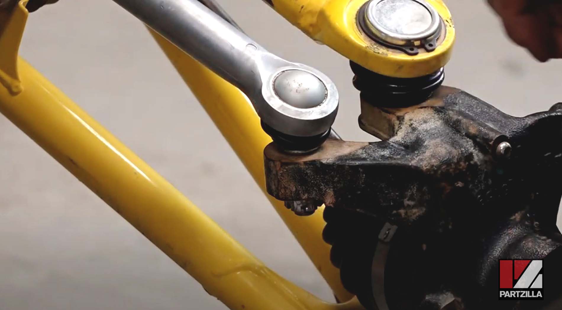
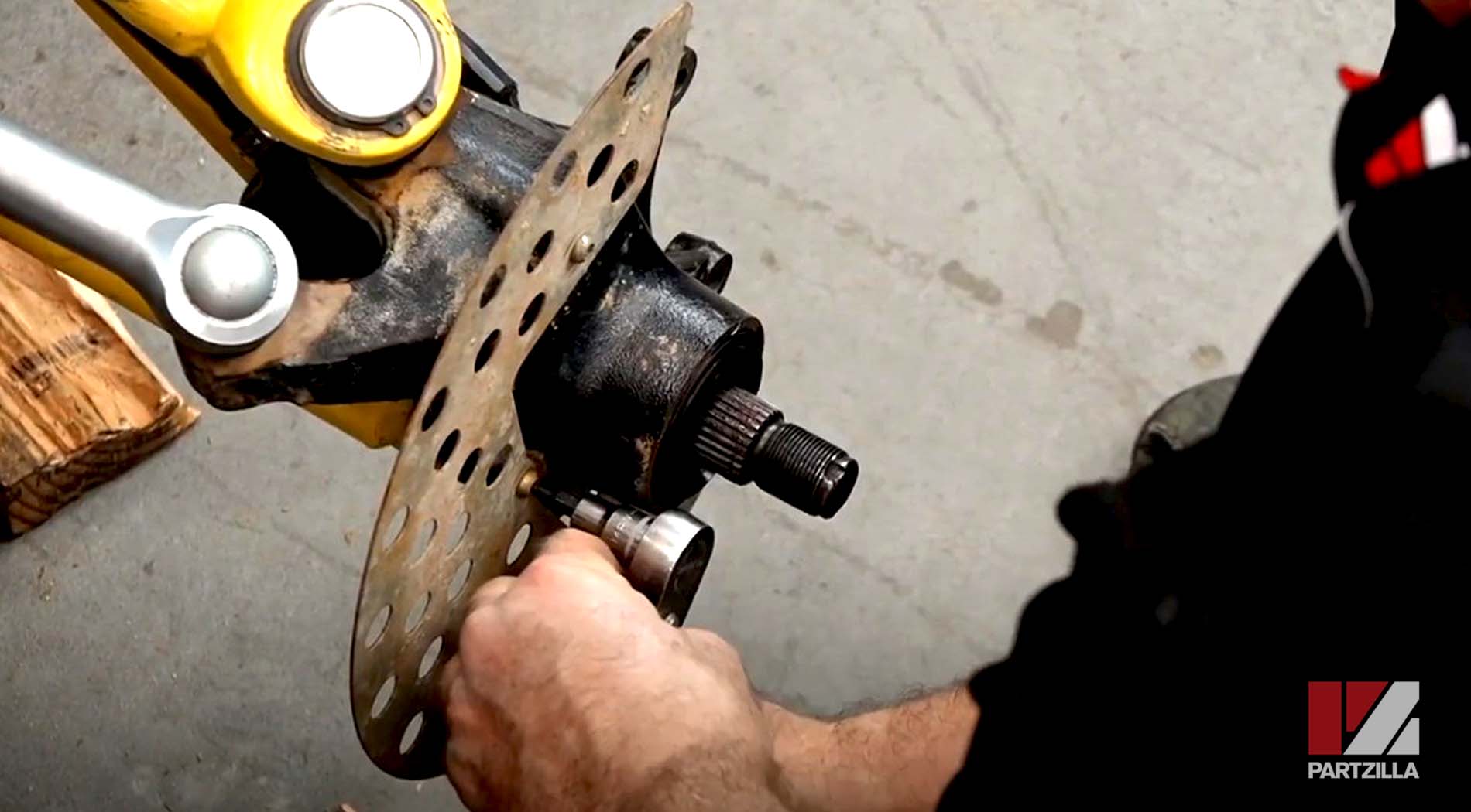
Step 27. Reinstall the wheel guard to the steering knuckle.
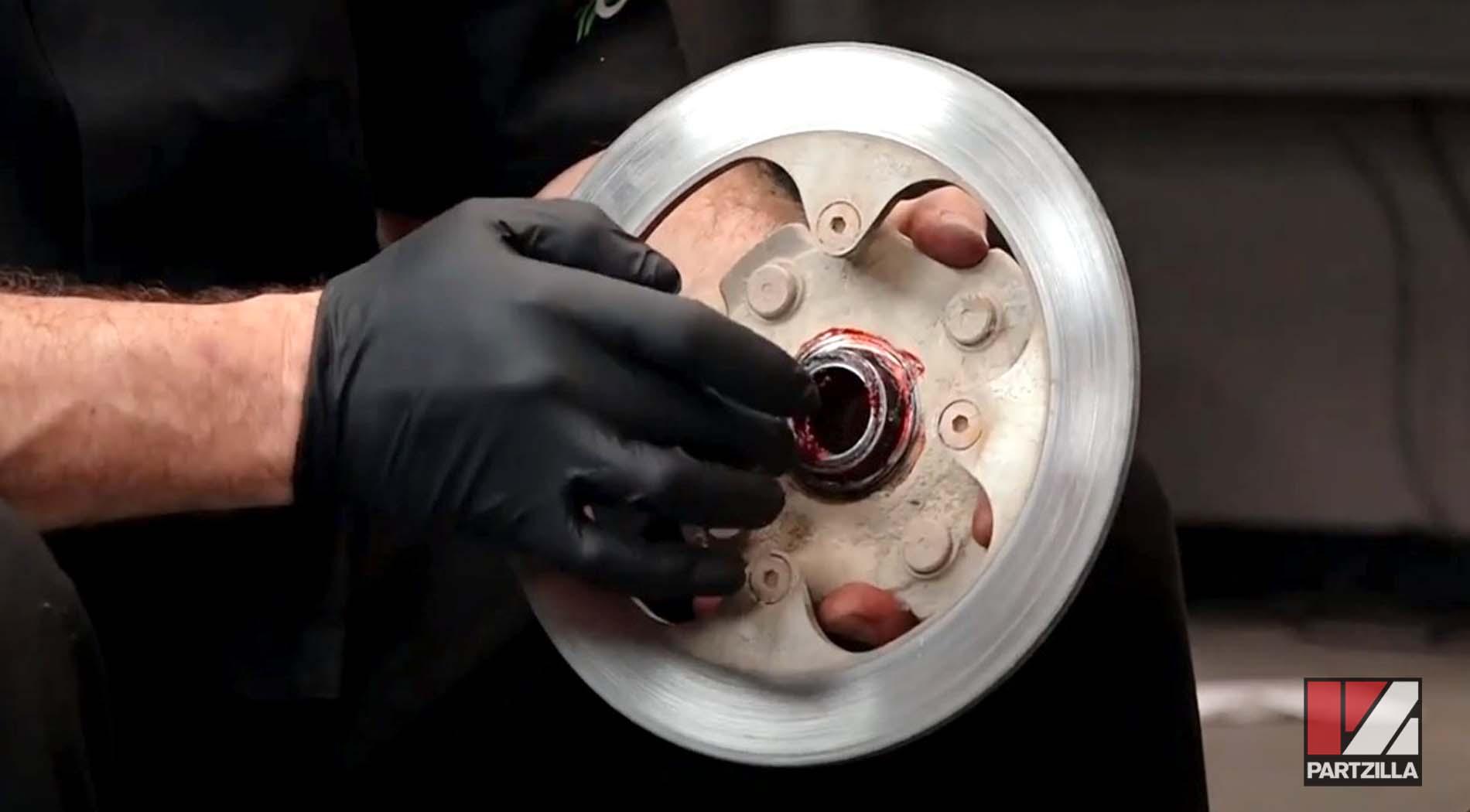
Step 28. Grease the inside of the wheel hub and reinstall it onto the steering knuckle.
Step 29. Reinstall the axle bolt and washer, and tighten them as much as possible, then torque the 32mm axle nut to 268 foot-pounds and stake it in place.
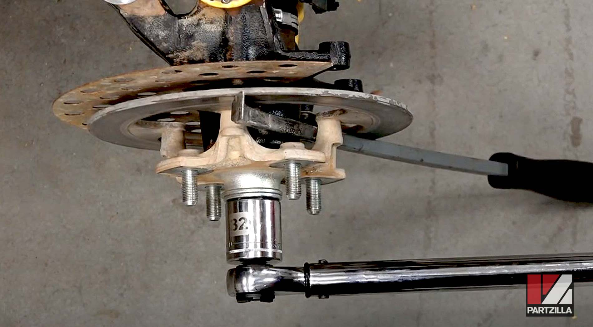
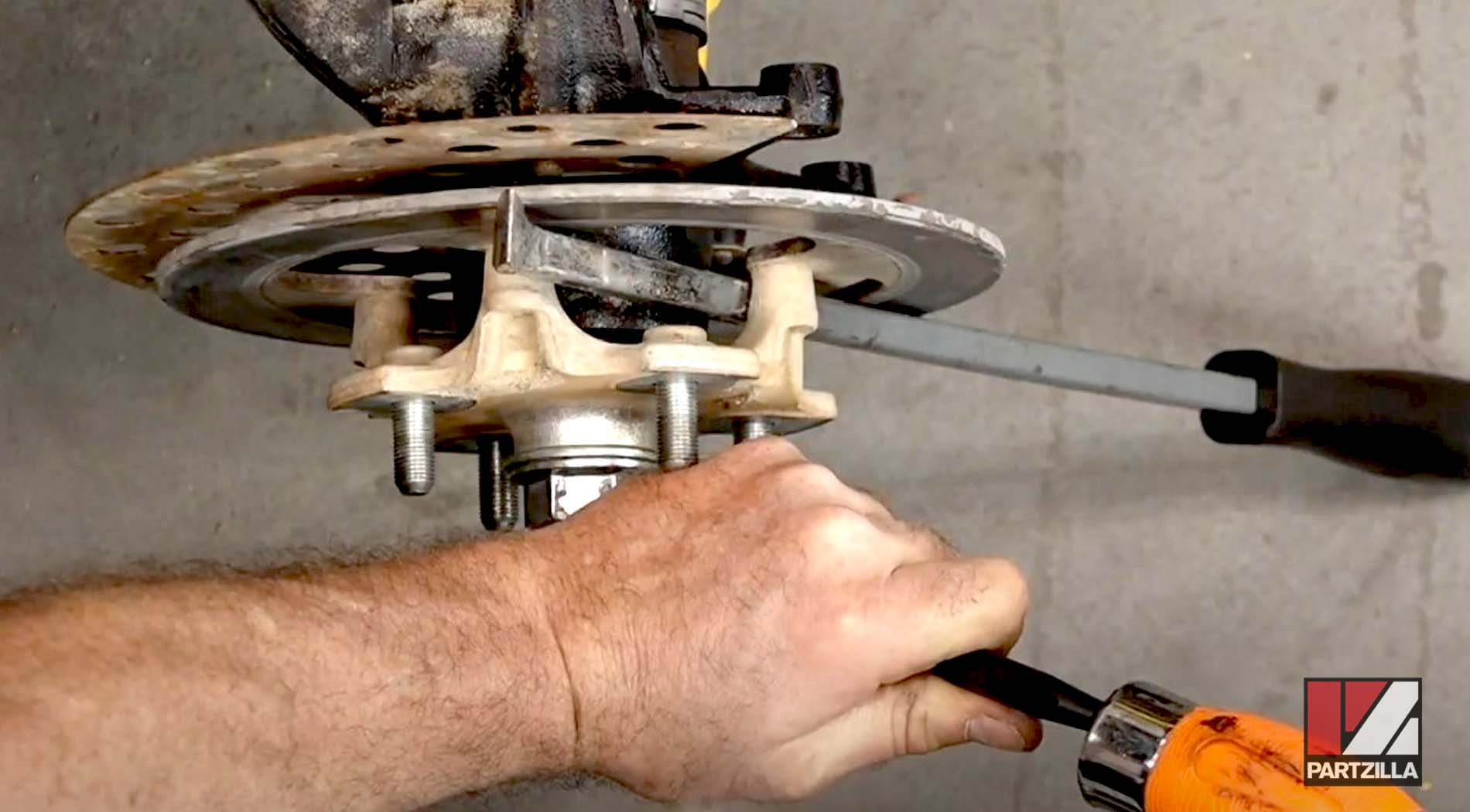
Step 30. Refasten the brake hose bracket (10mm bolt) to the lower A-arm, then reinstall the brake caliper assembly and torque the 14mm mounting bolts to 35 foot-pounds.
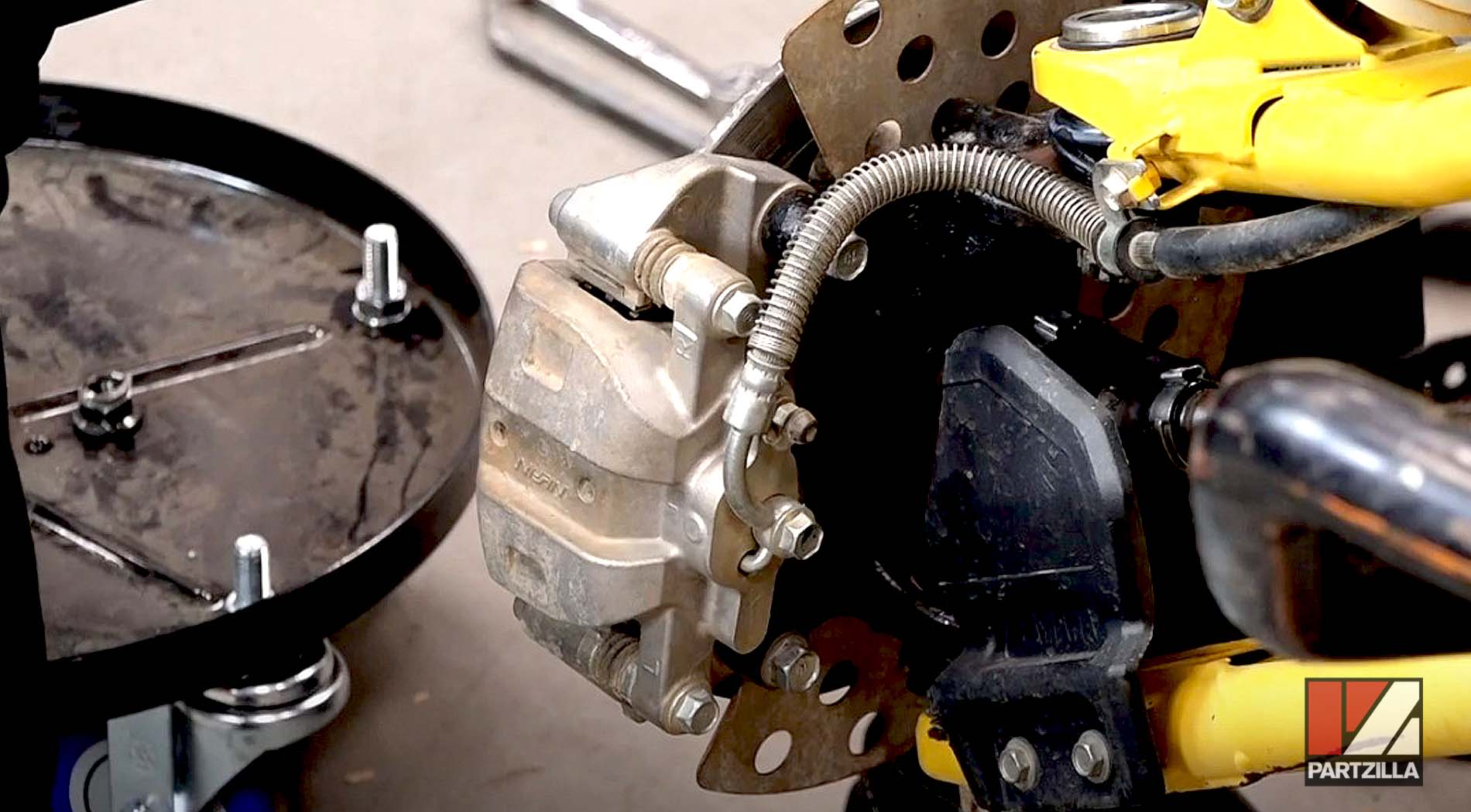
Step 31. Reinstall the front wheel, then lower the vehicle to the ground and you're done.
