How to Replace a Kawasaki Mule PRO-FXT Starter Motor
Replacing a starter motor in a Kawasaki UTV requires the arduous task of removing the clutch assemblies to access the starter motor.
Your local Kawasaki dealership would charge you a hefty sum for that, so doing it yourself will save you a lot of money. Watch the video above and follow the steps below to replace the starter motor in a Kawasaki Mule PRO side-by-side.
Tools and Parts - Kawasaki Mule Starter Replacement
- Ratchet and extensions
- 6mm, 8mm, 10mm, 12mm, 13mm sockets
- Screwdrivers
- Pliers
- Pry bar
- Torque wrench
- Contact/brake cleaner
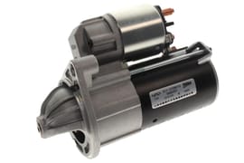
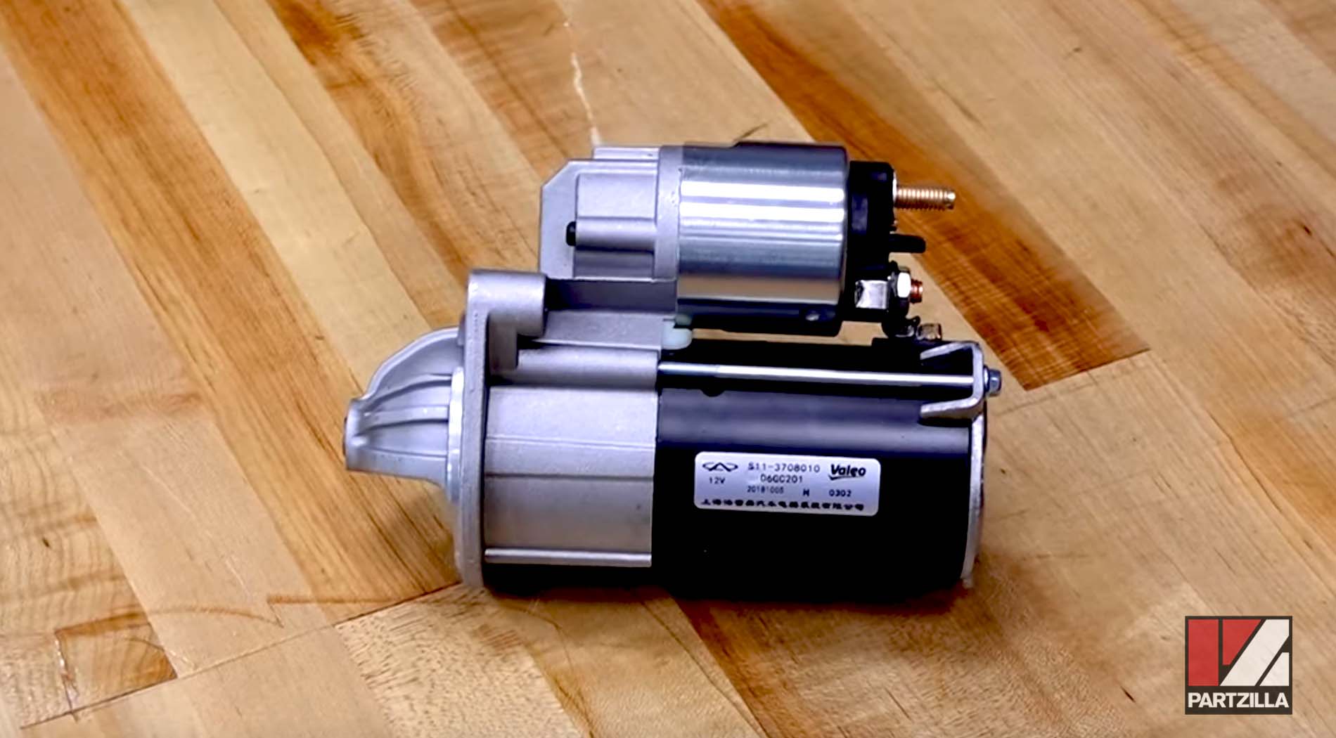
- Starter motor
- High temperature bonding compound
- Blue threadlocker


How to Remove Kawasaki Mule PRO-FXT Starter Motor
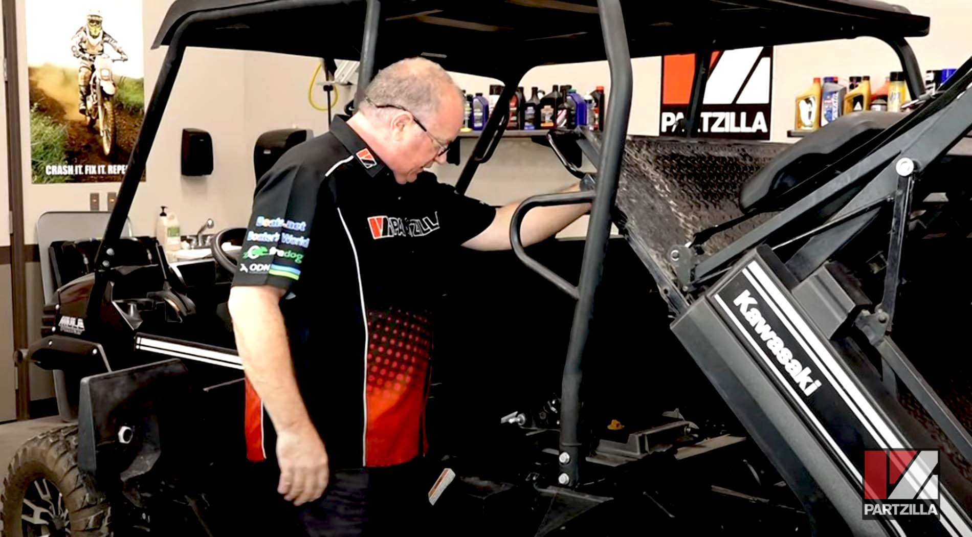
Step 1: Unlatch the rear cargo bed, and tilt it up and out of the way.
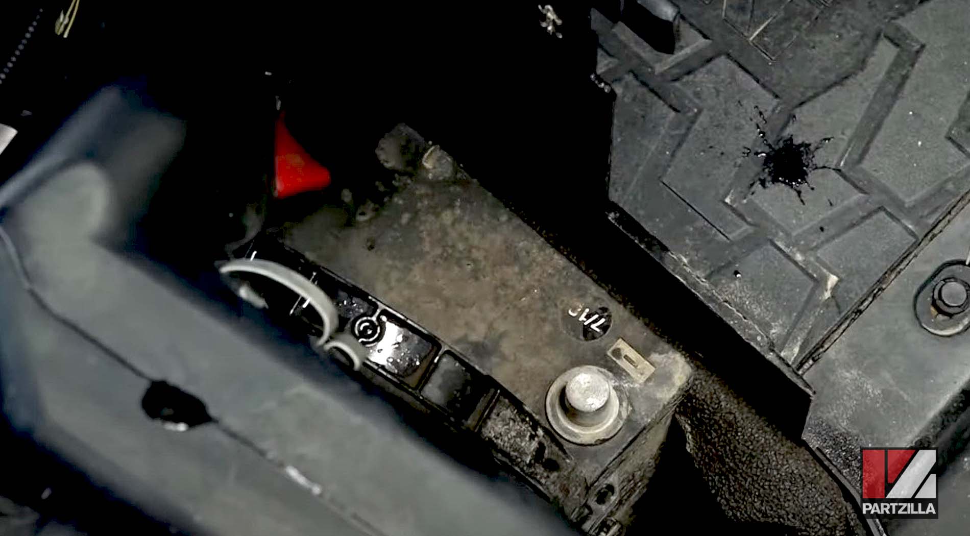
Step 2: Remove the battery cover, and disconnect the negative cable from the battery.
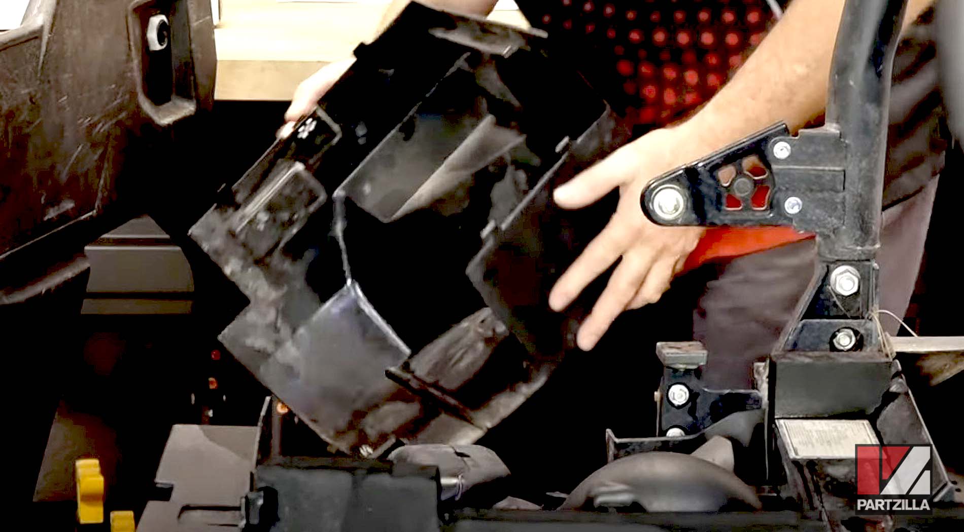
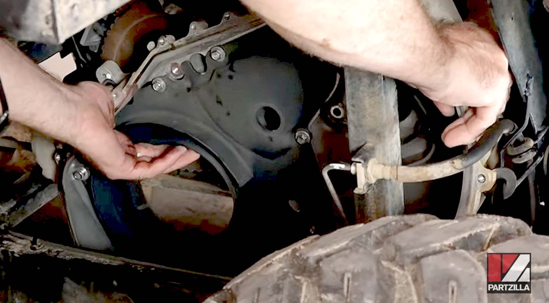
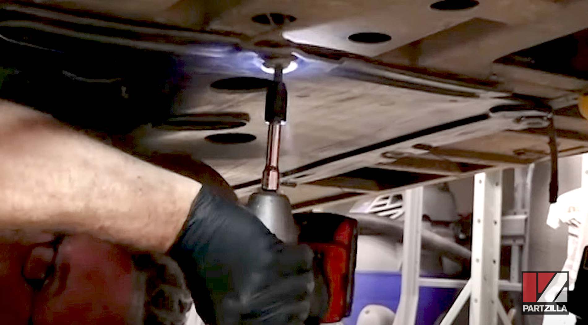
Step 3: Remove the fifteen 10mm bolts holding the outer converter cover, followed by the cover itself.
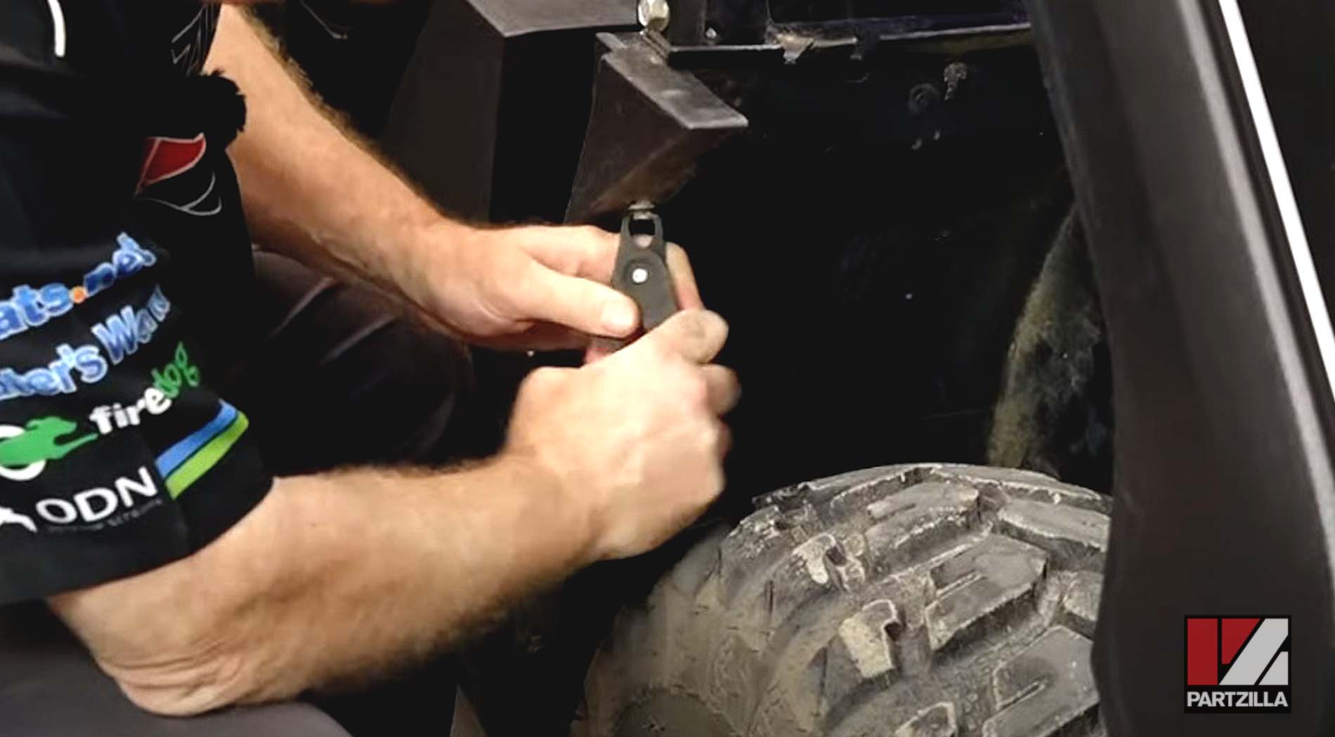
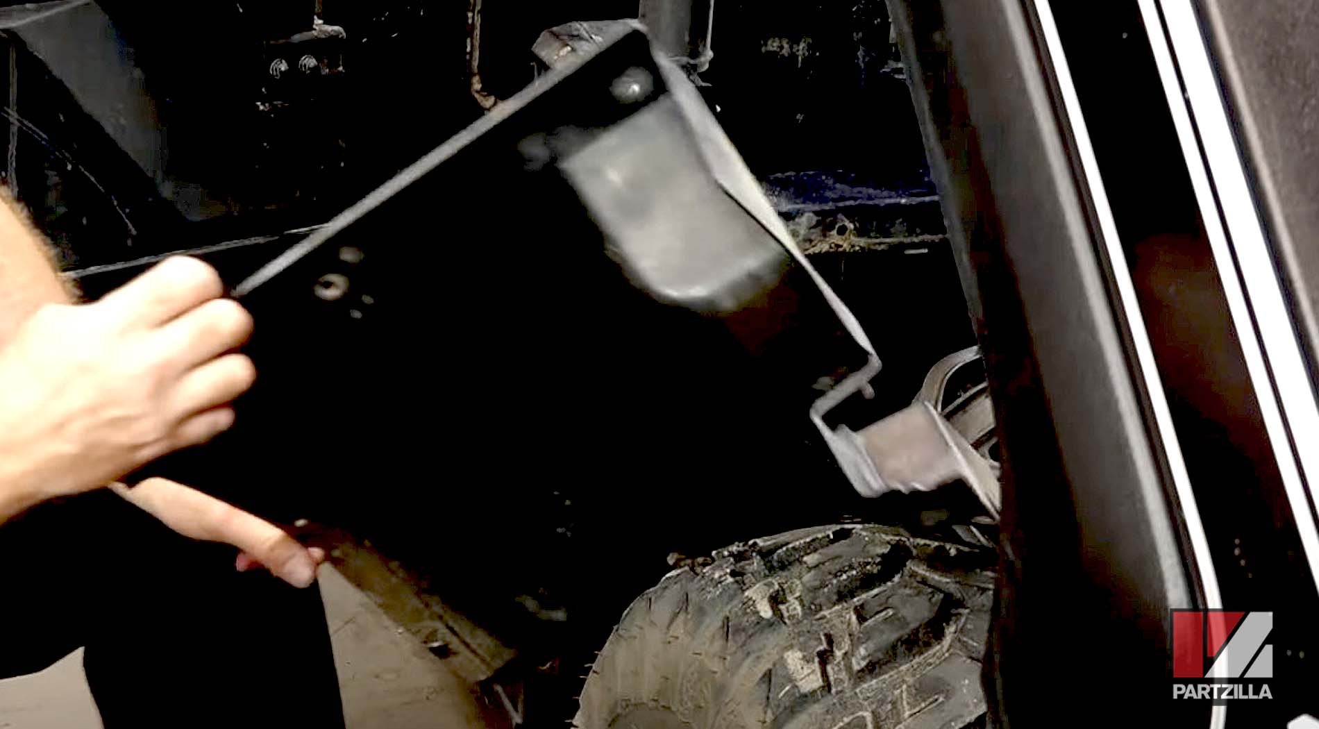
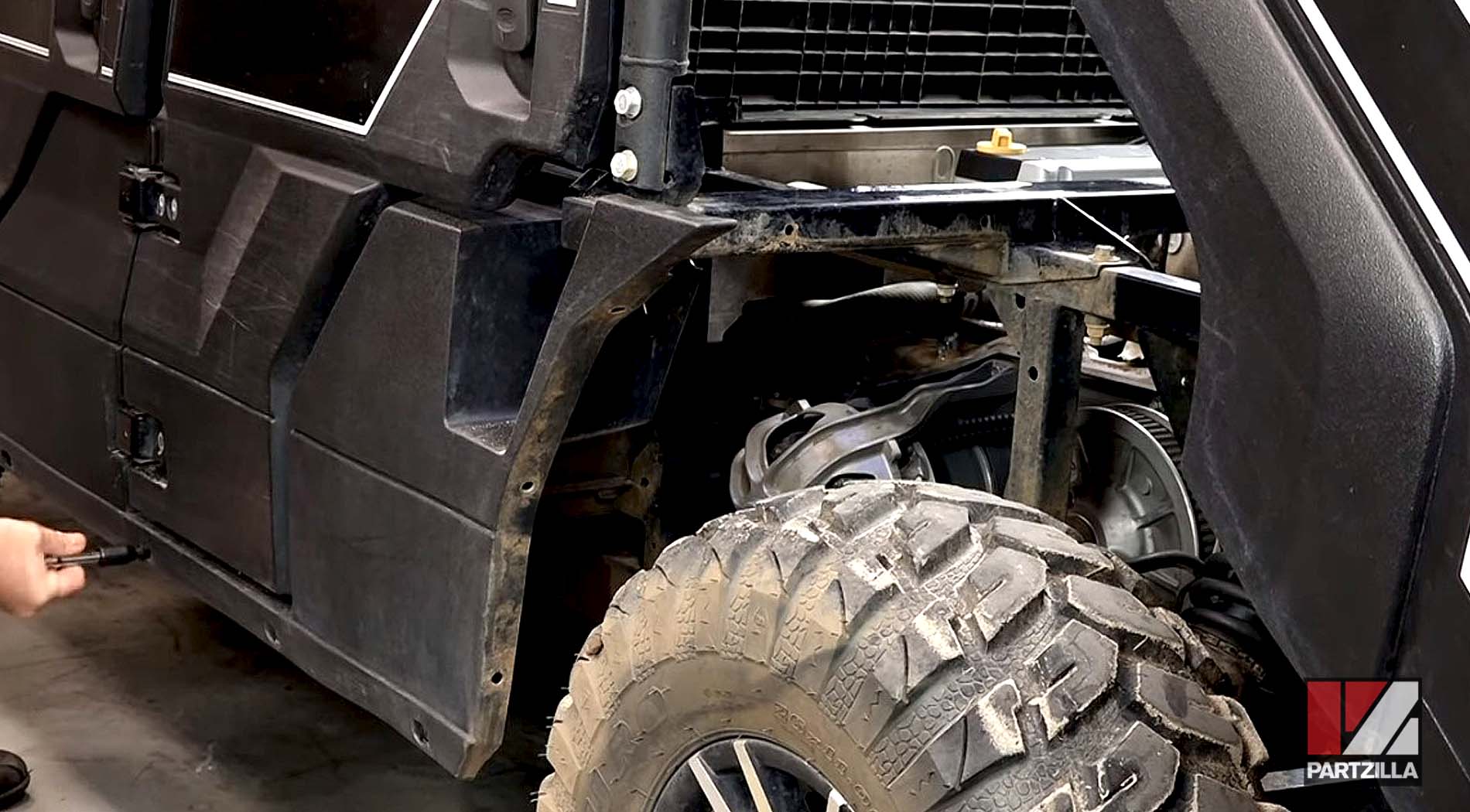
Step 4: Remove the inner fender in front of the left-rear wheel and the side panel to get better access to the converter cover.
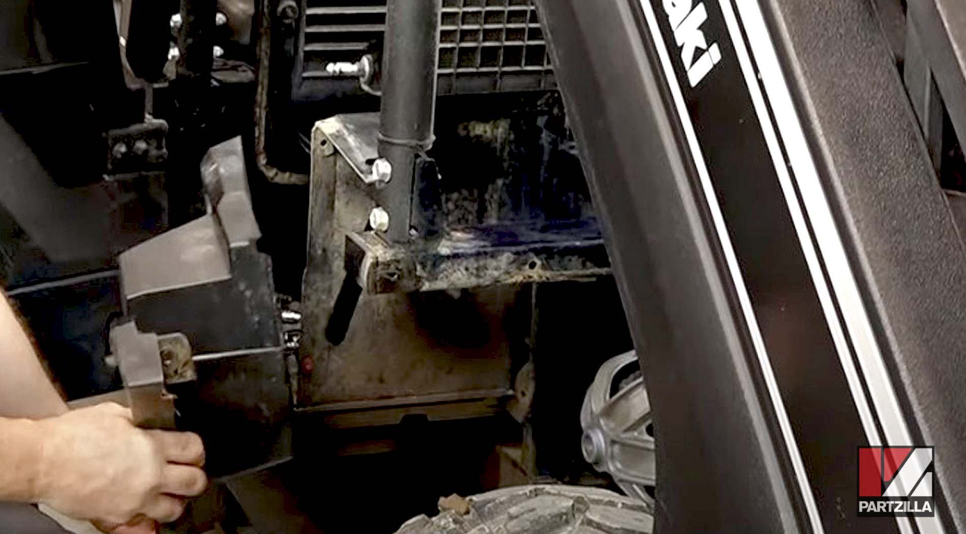
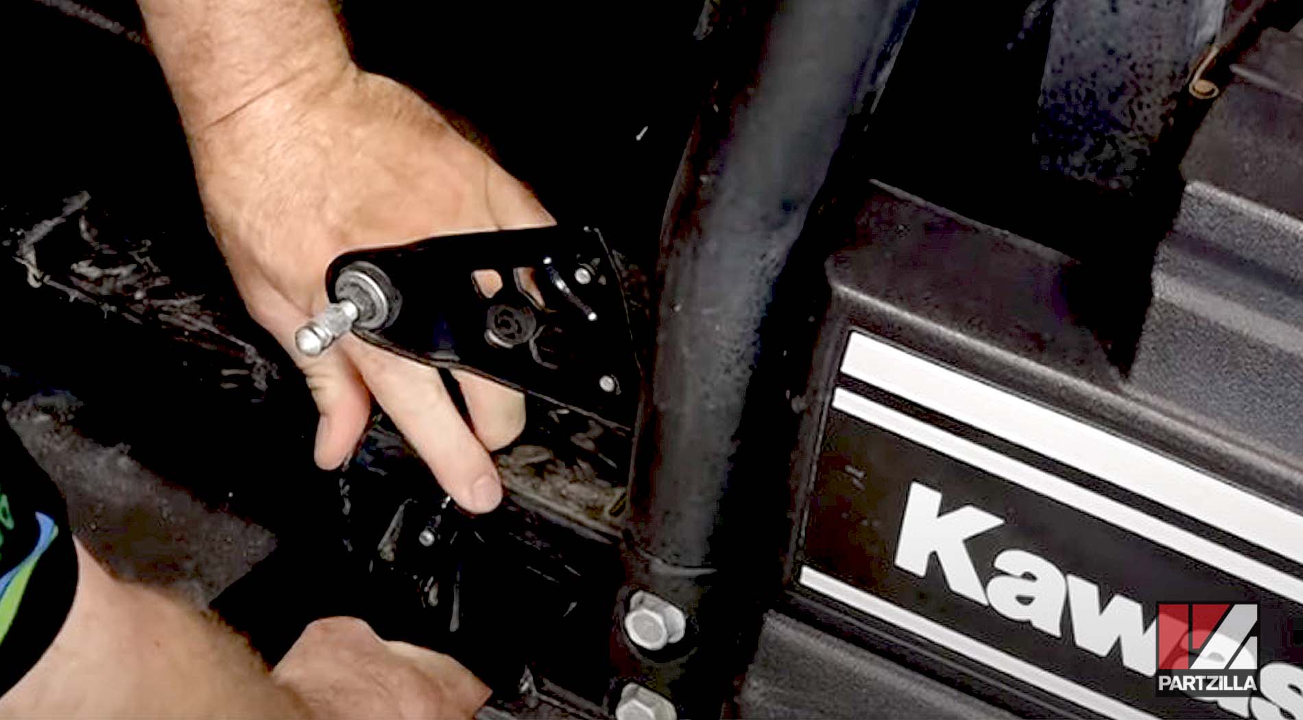
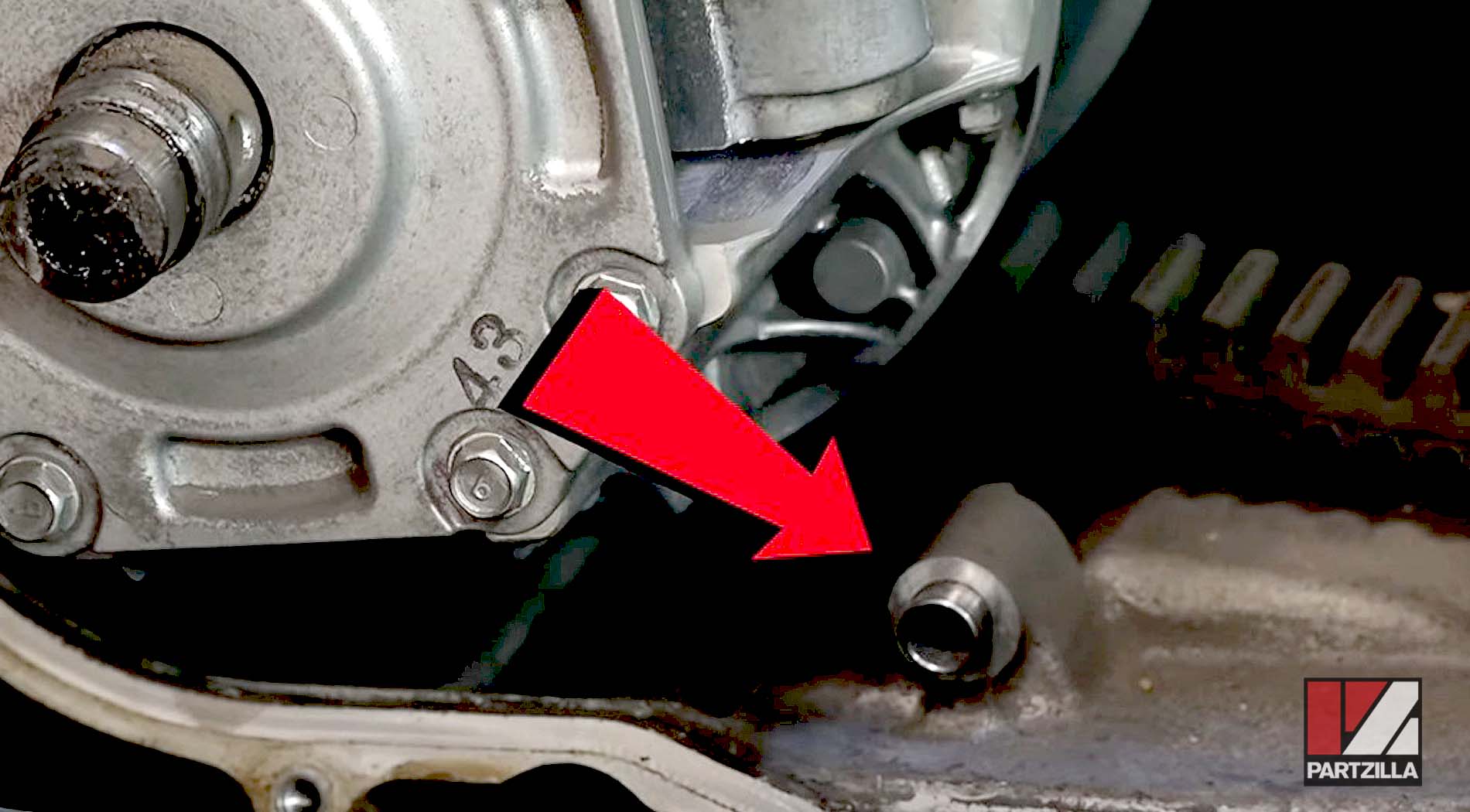
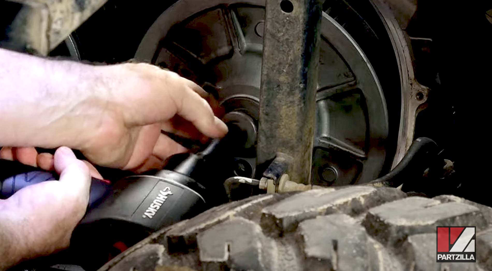
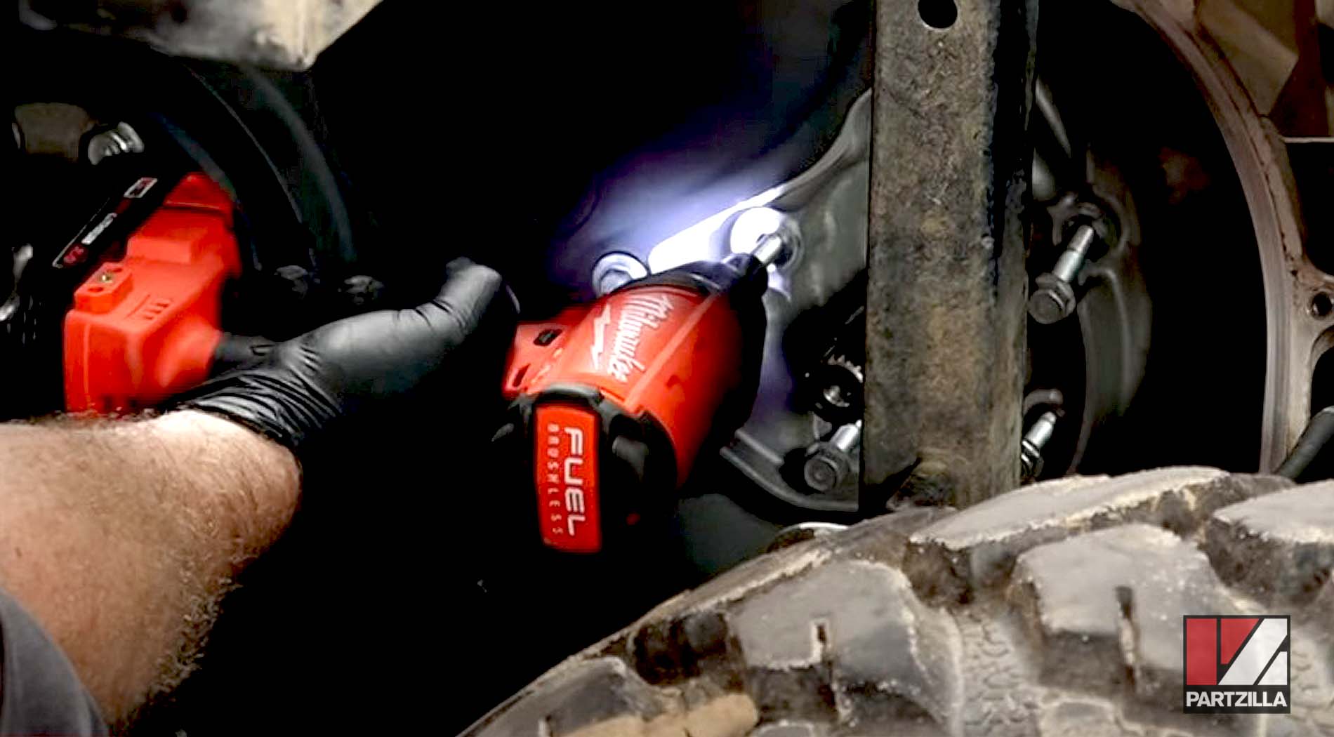
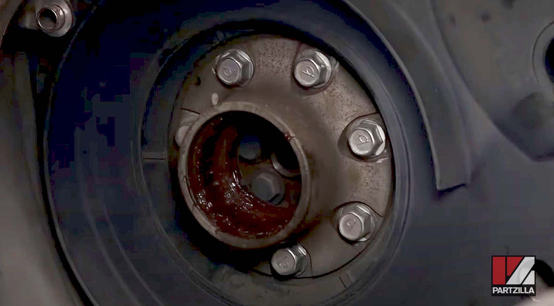
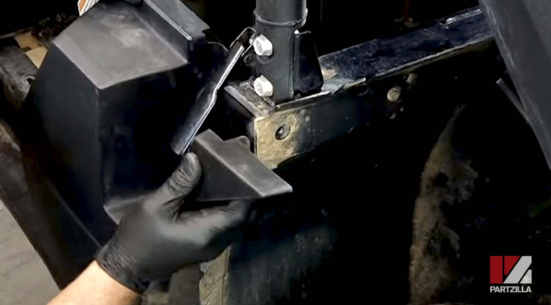
Step 5: Remove the three 12mm bolts holding the bearing carrier, followed by the carrier itself.
NOTE: Make sure not to lose the two dowel pins as you remove the bearing carrier.
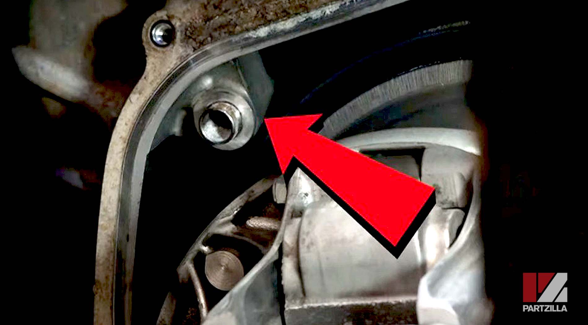
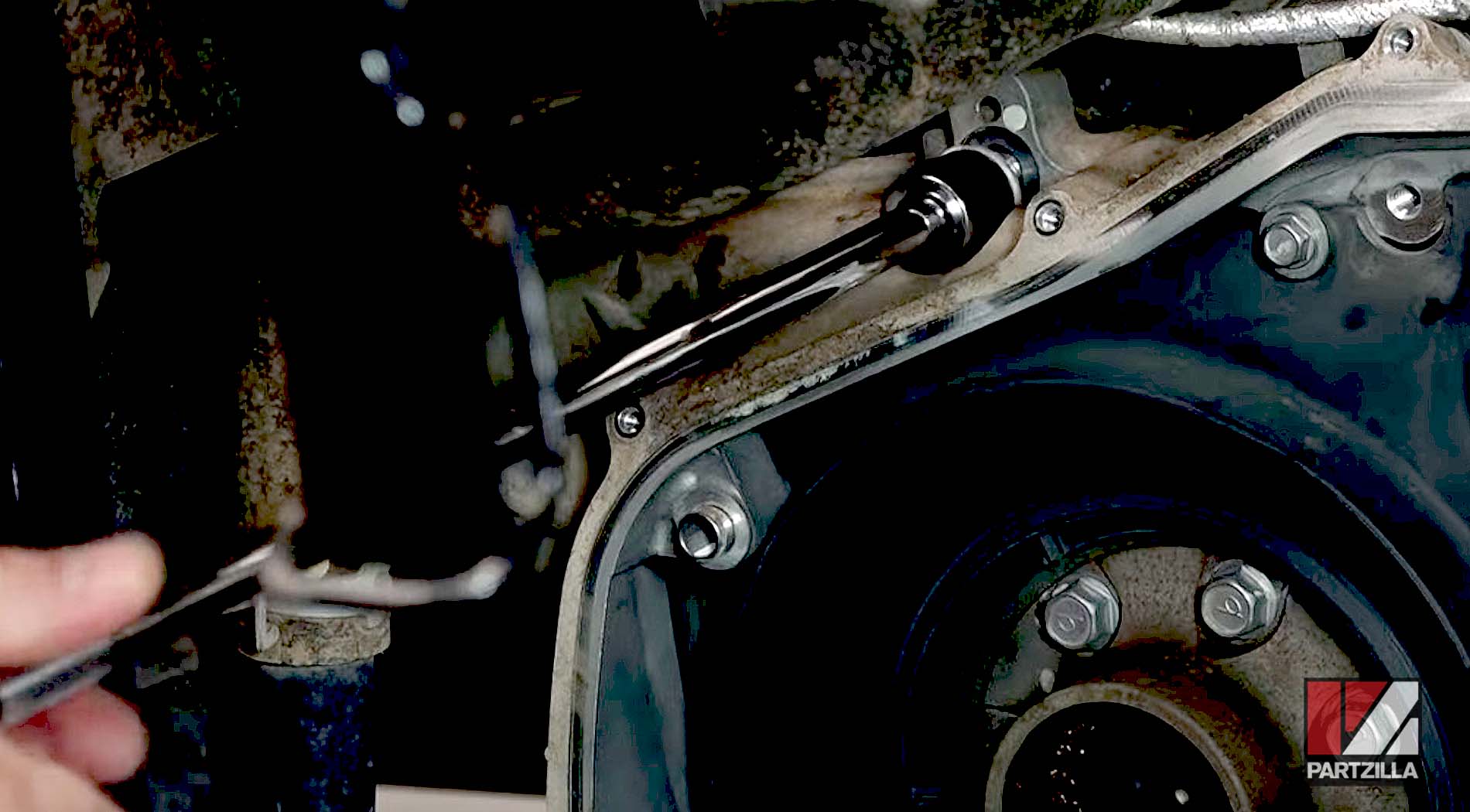
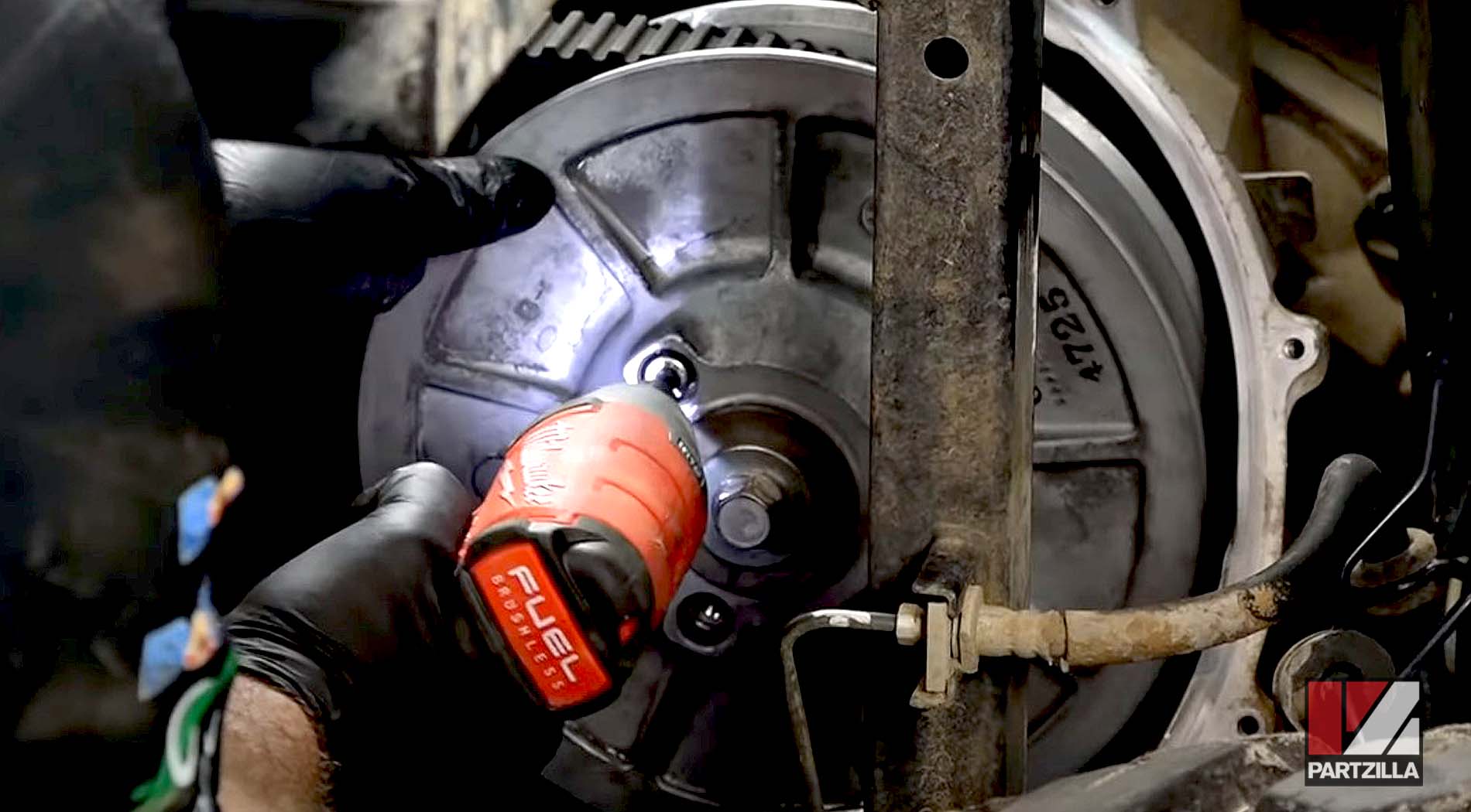
Step 6: Remove the driven clutch assembly center bolt and washer.
NOTE: The bolt has a reverse thread, so you'll have to turn it clockwise to loosen it.
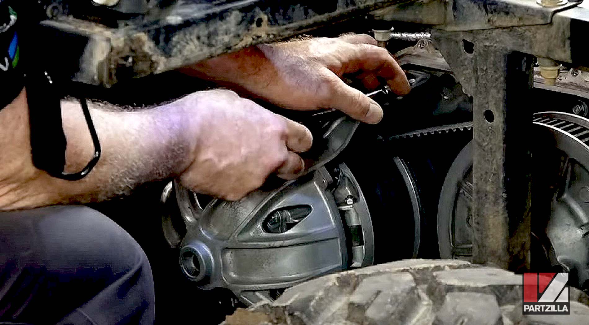
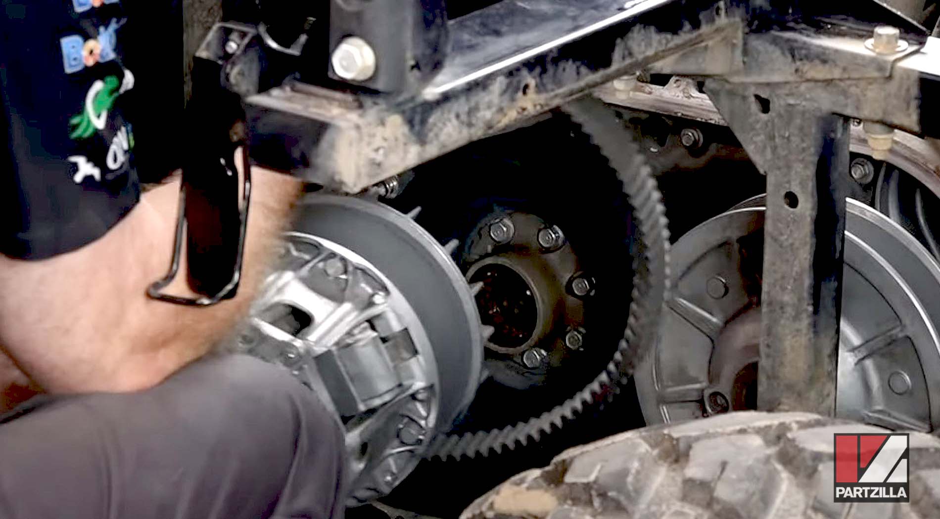
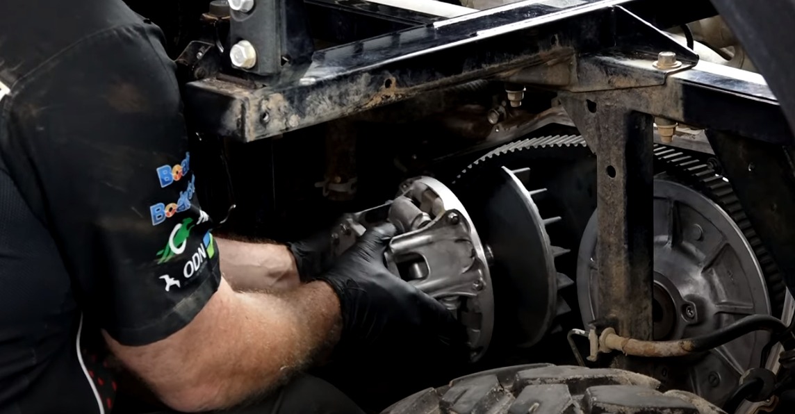
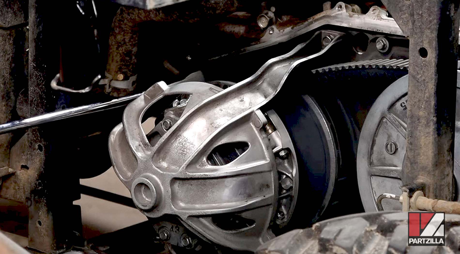
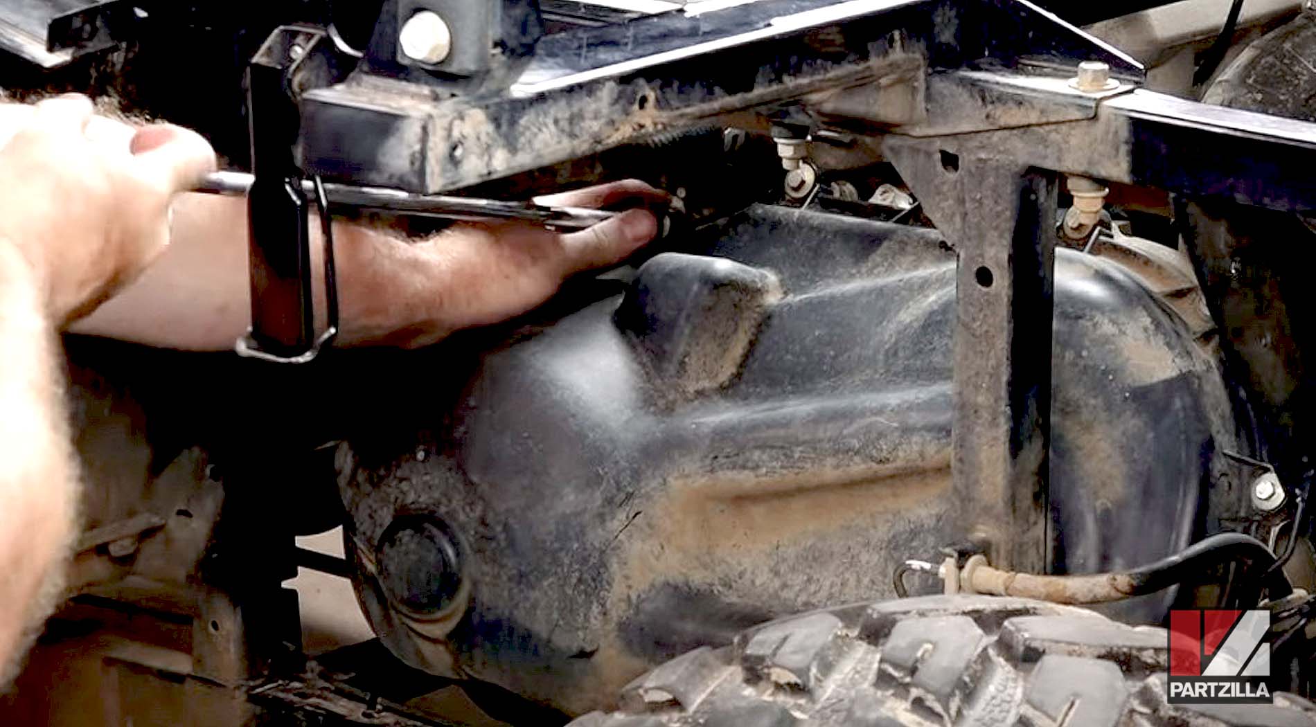
Step 7: Loosen the driven clutch assembly by carefully prying it out from the transmission input shaft.
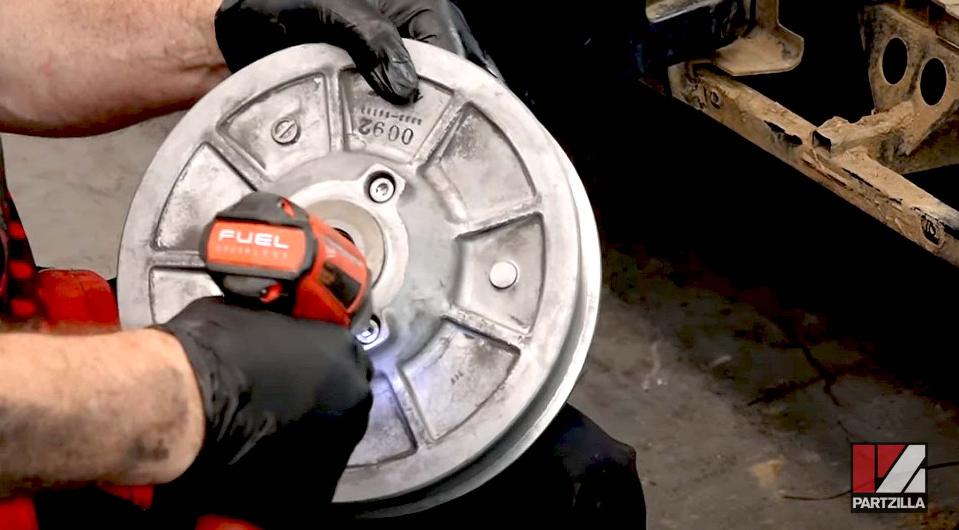
Step 8: Loosen the drive clutch assembly by pulling it out from the engine.
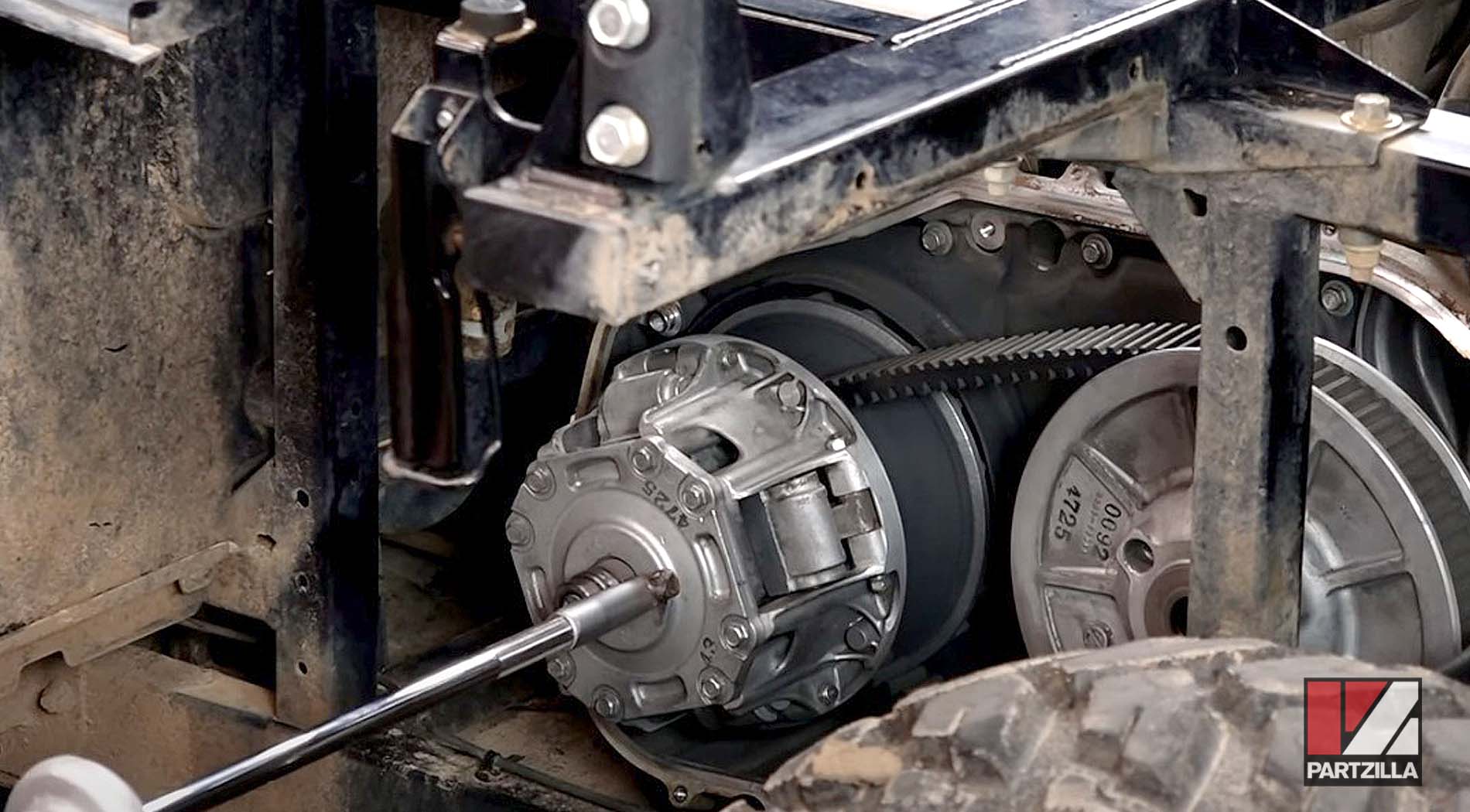
NOTE: Kawasaki makes a specific tool for removing the drive clutch assembly, but it can be done without it.
Watch the clip below to see how to do this step without having to buy the special tool.
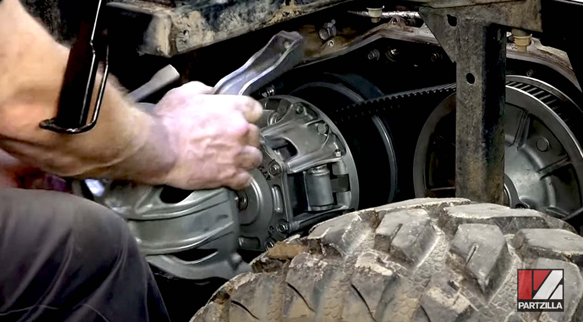
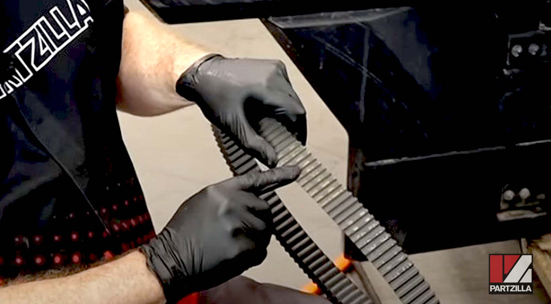
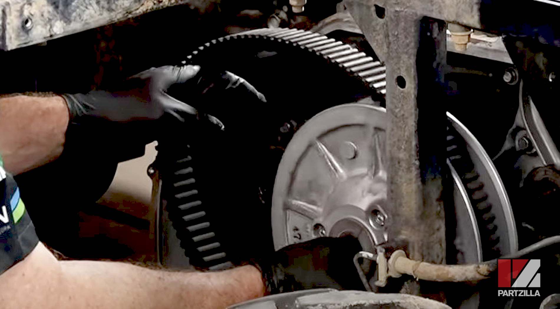
Step 9: Remove the drive clutch assembly and the driven clutch assembly, followed by the drive belt.
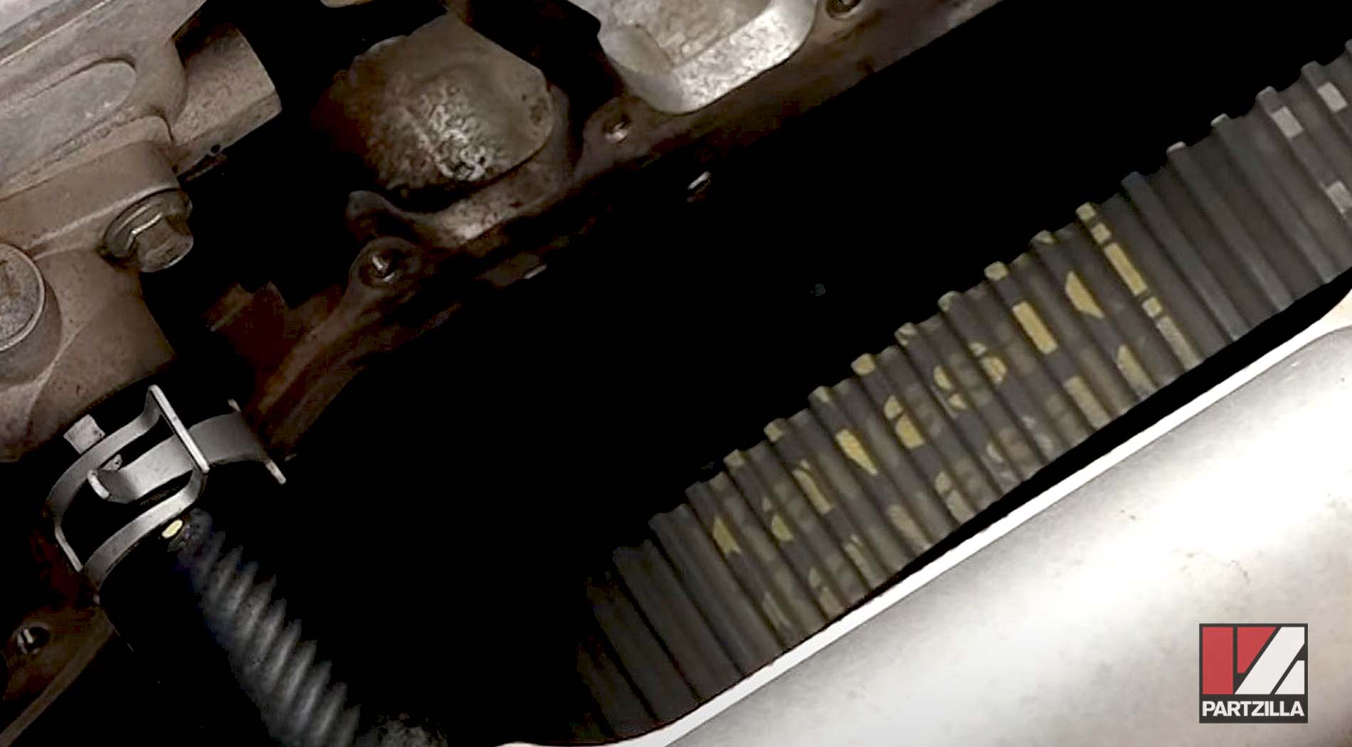
PRO TIP: Note which direction the belt was installed, so you can reinstall it in the right direction later.
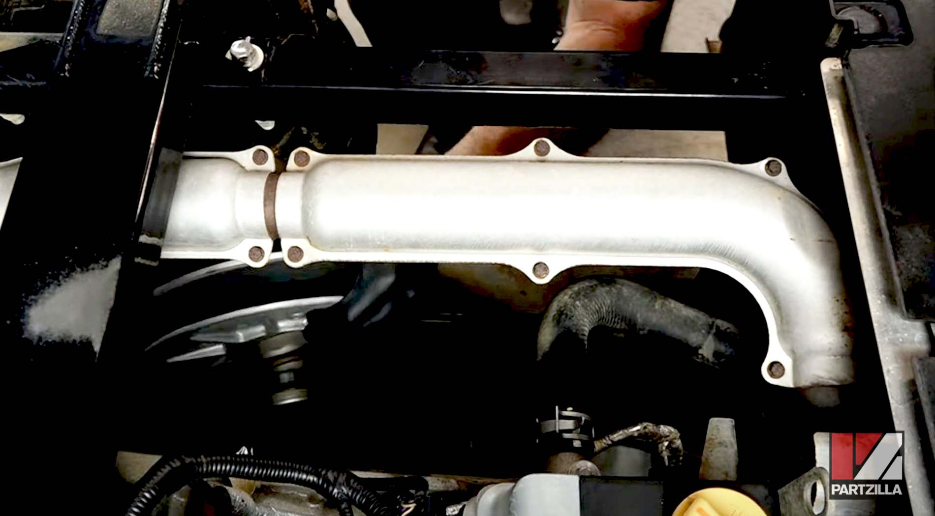
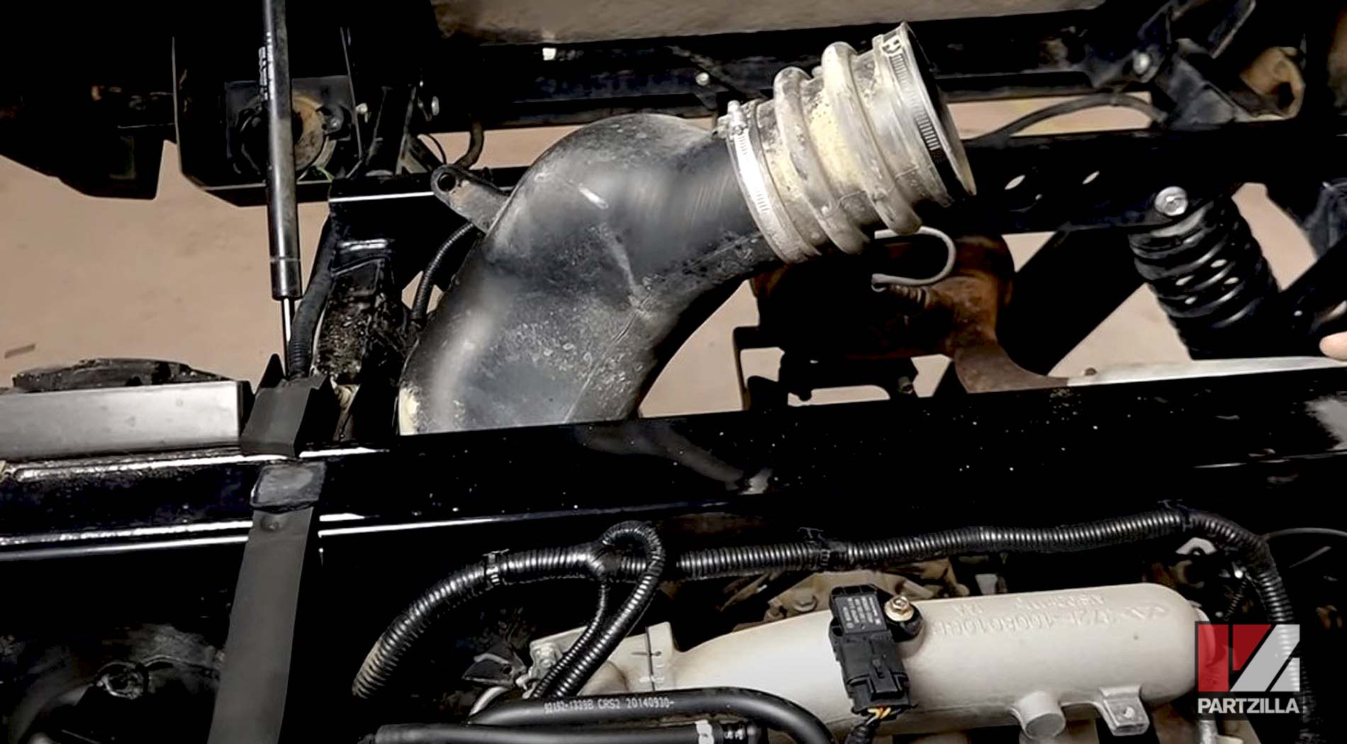
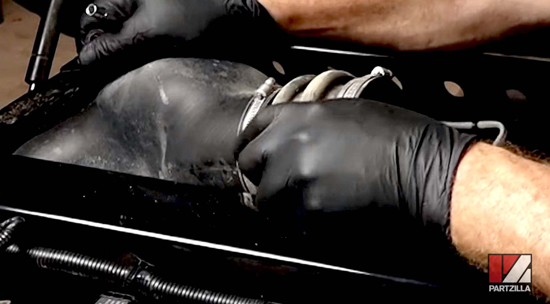
Step 10: Remove the air exhaust duct and the air intake duct.
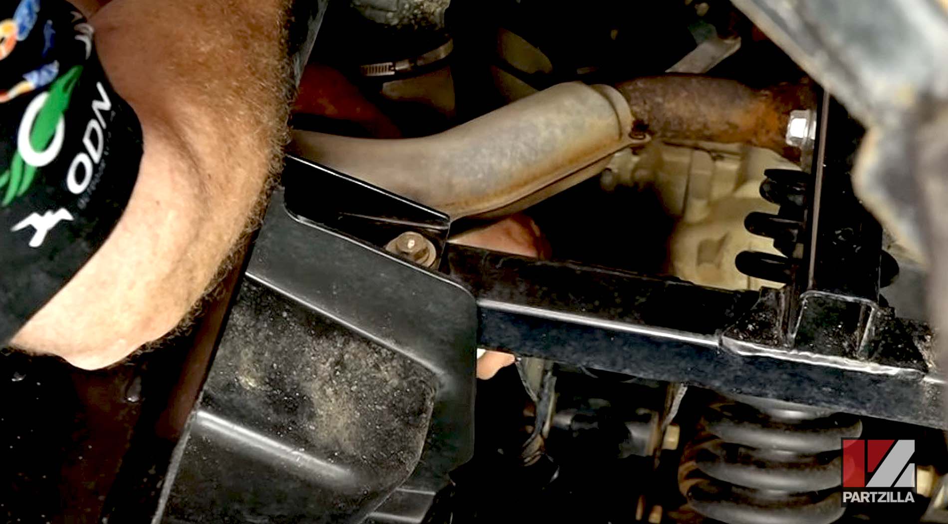
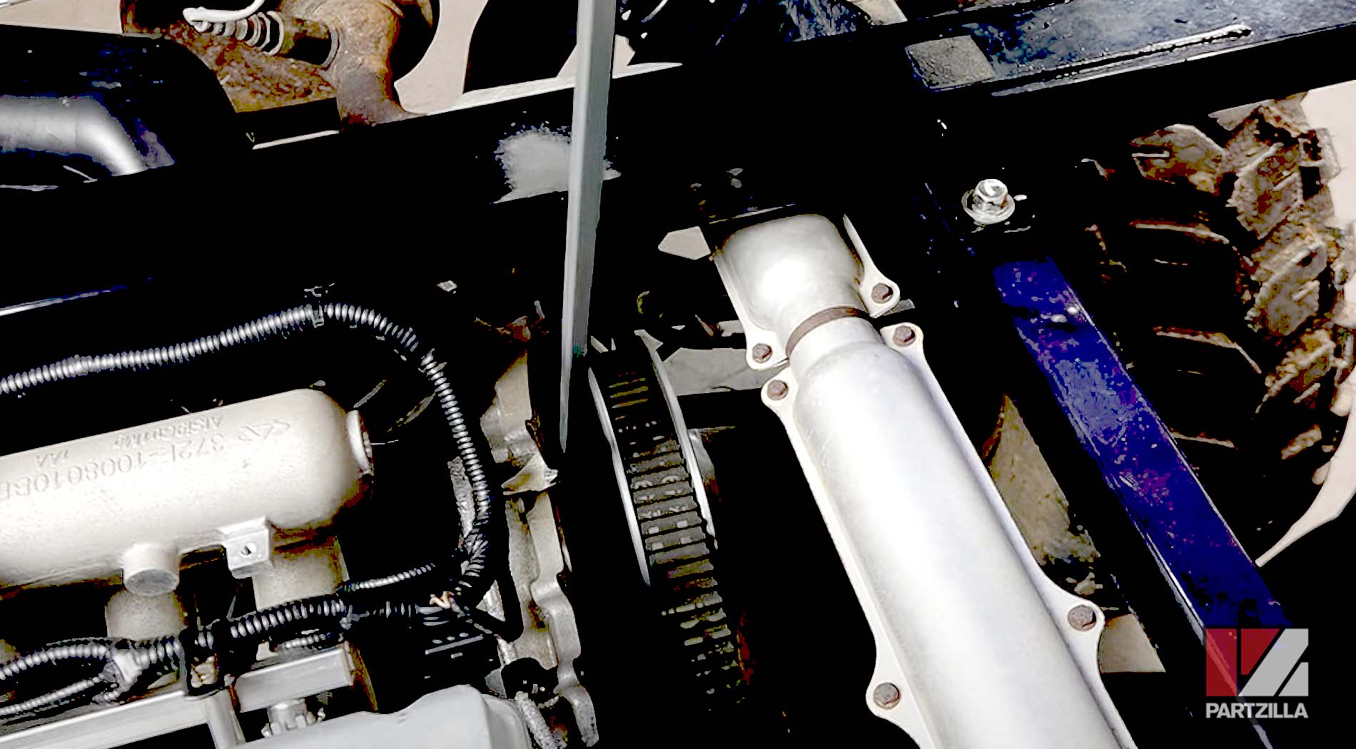
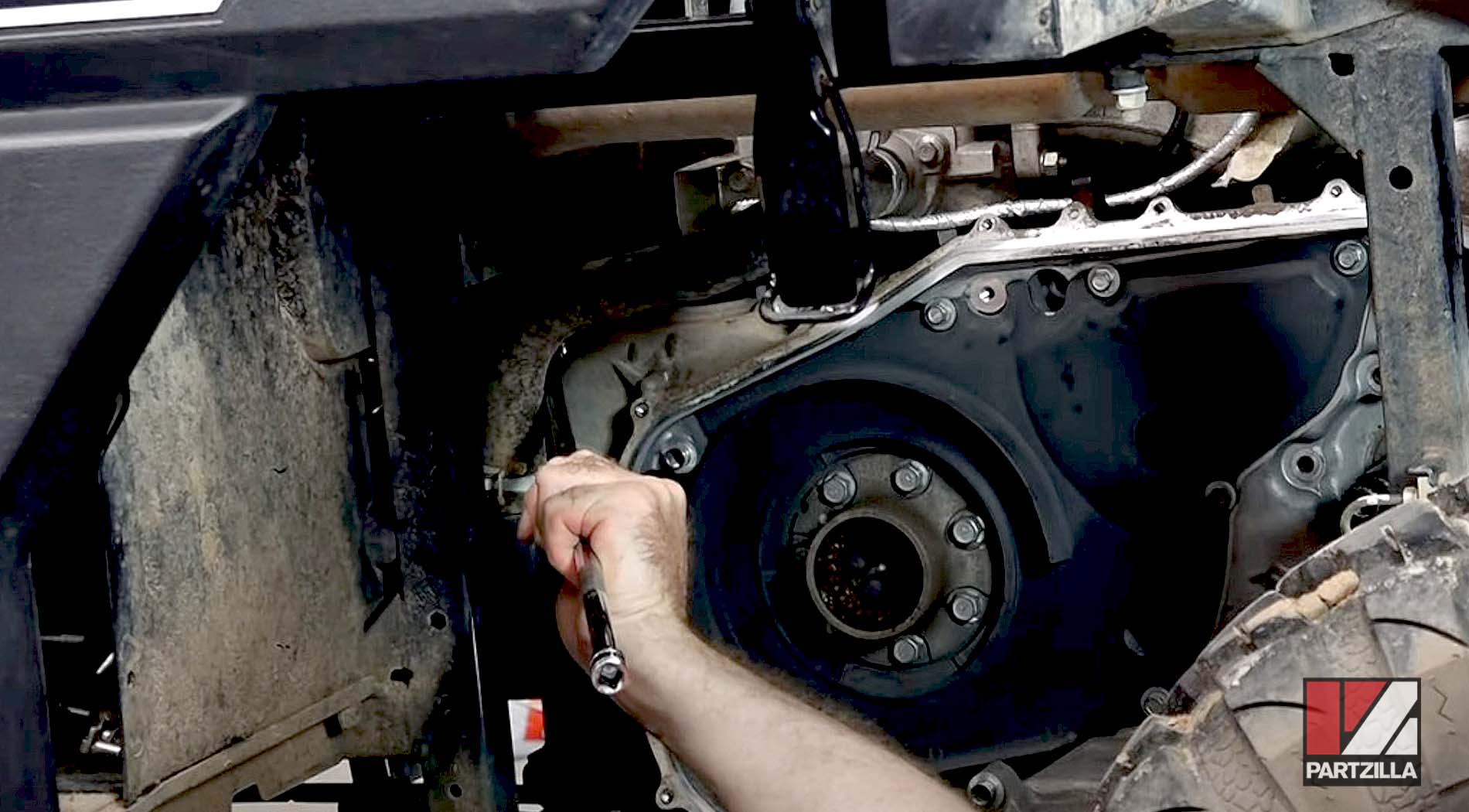
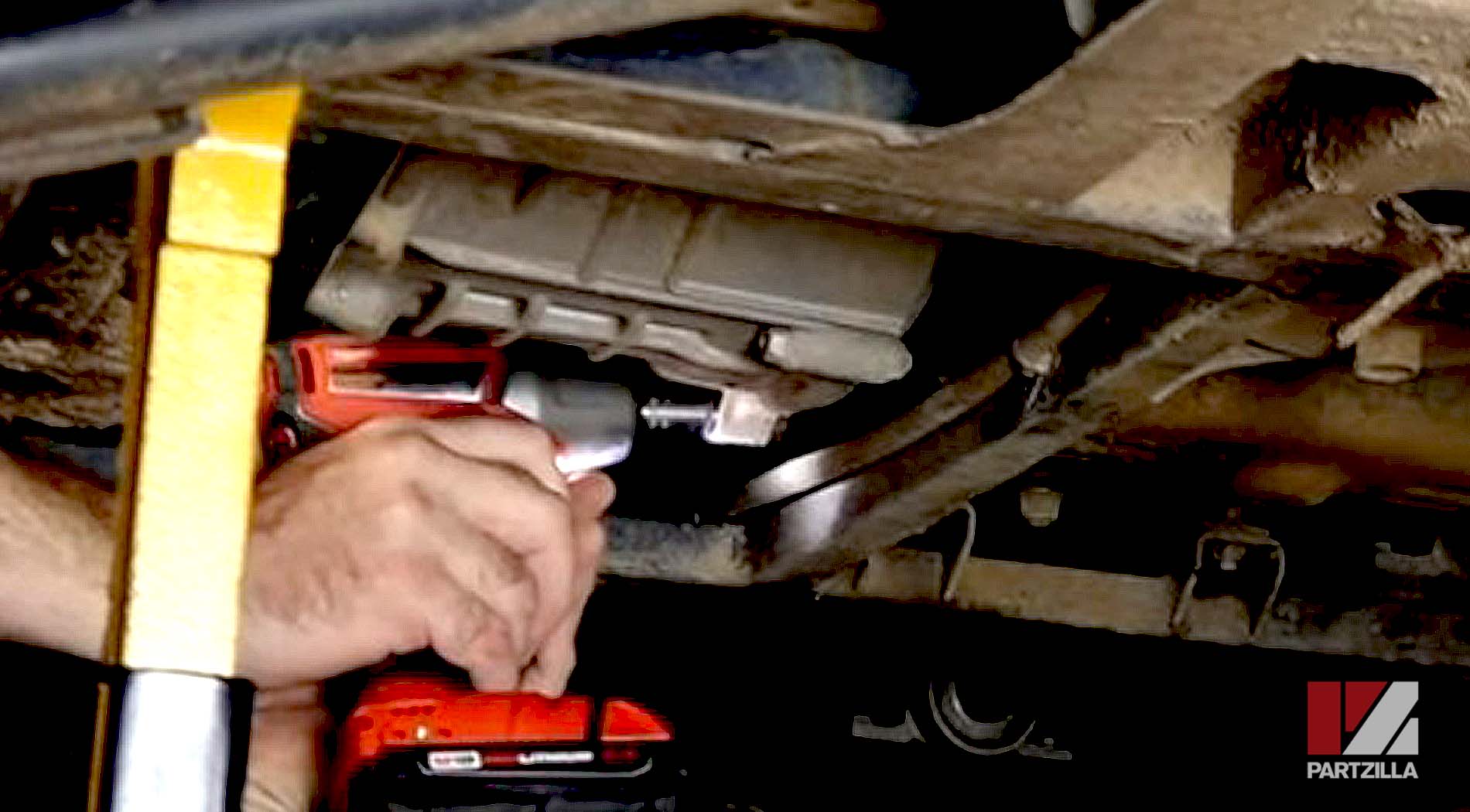
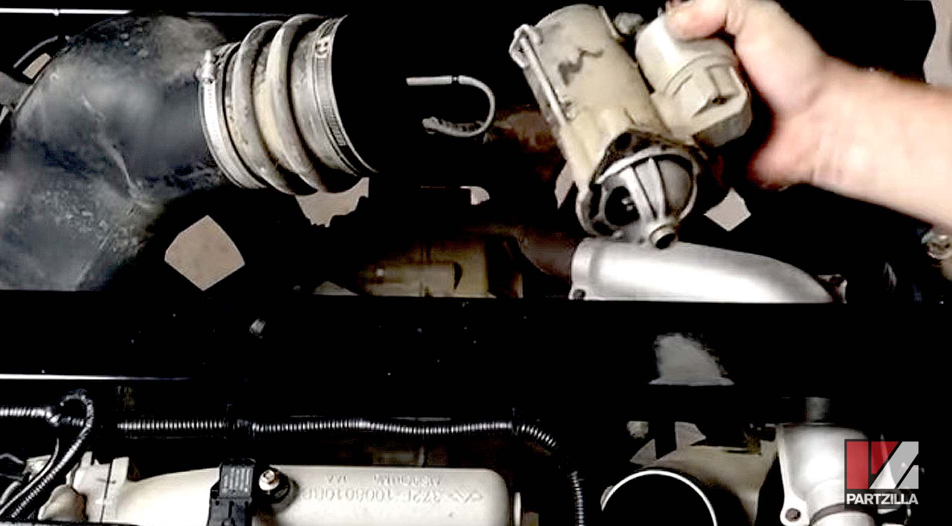
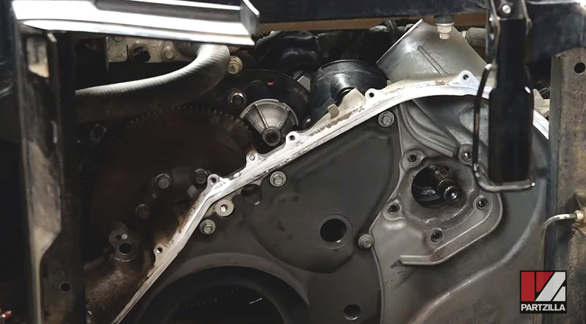
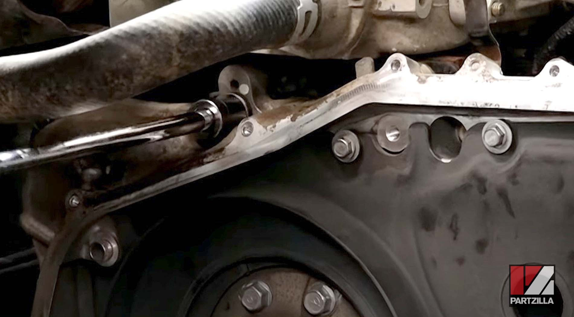
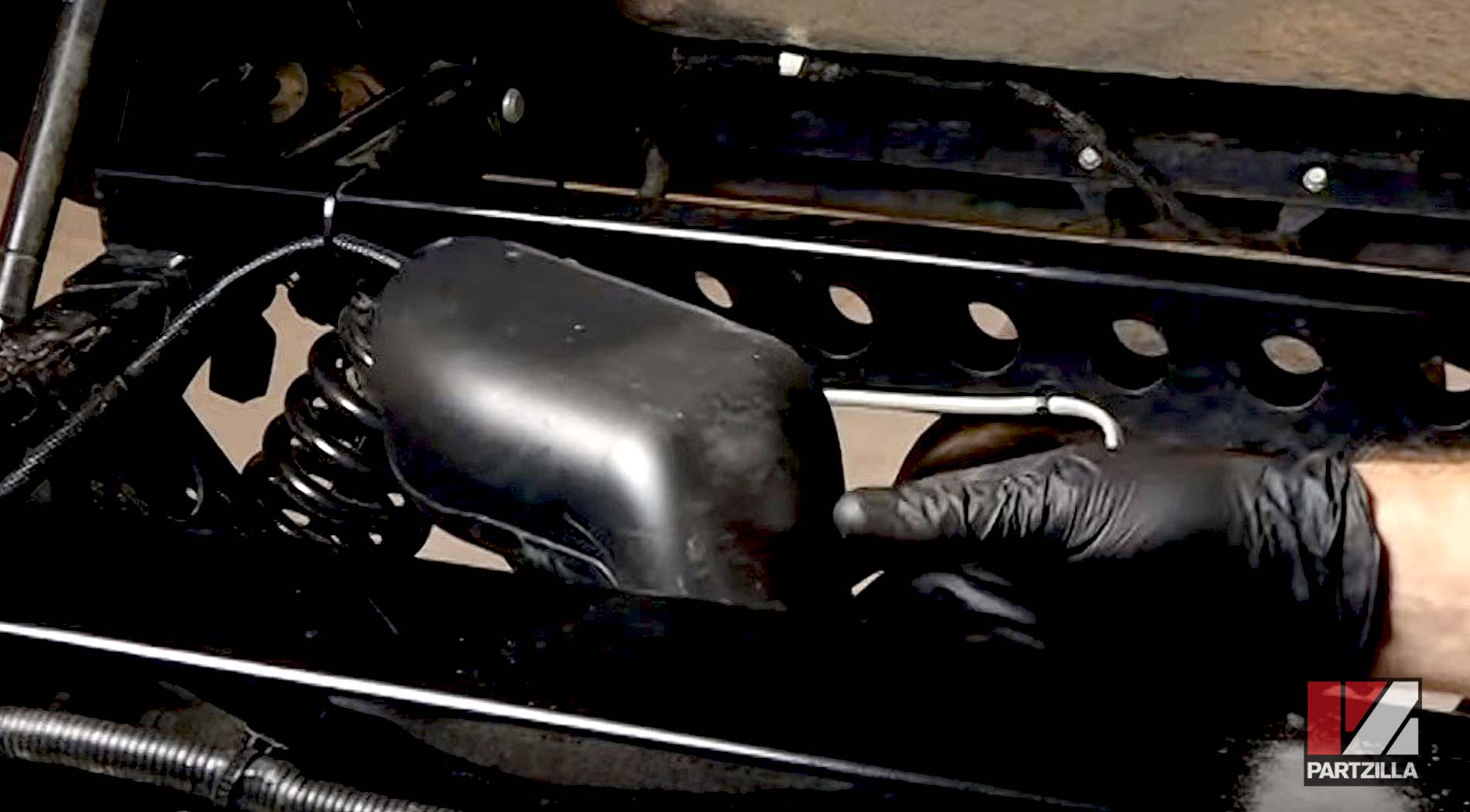
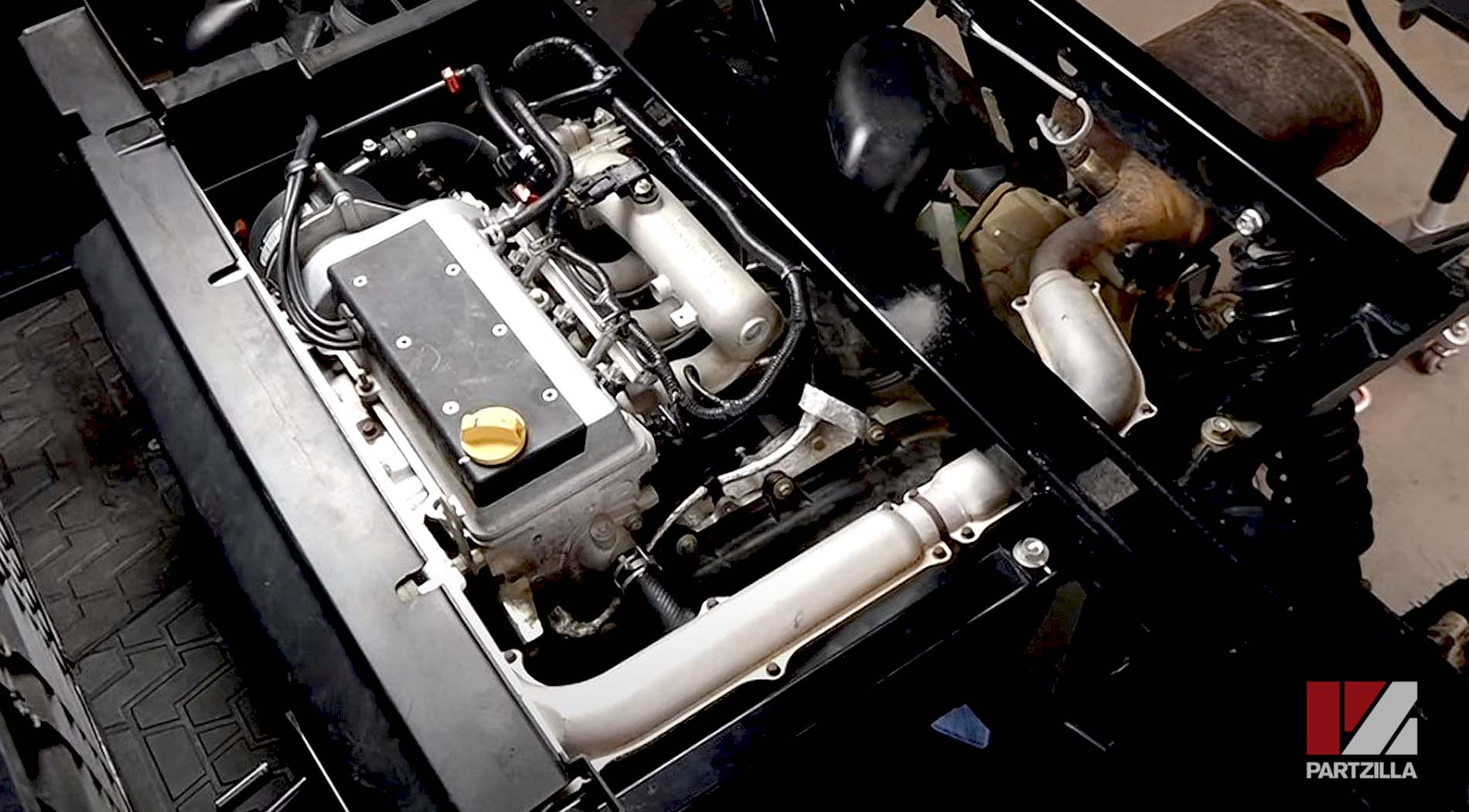
Step 11: Remove all the M8 bolts from the converter cover, and the single 17mm oil channel bolt at the top. Pry the converter cover free from the engine, and pull it out of the way of the plate on which the starter motor is mounted.
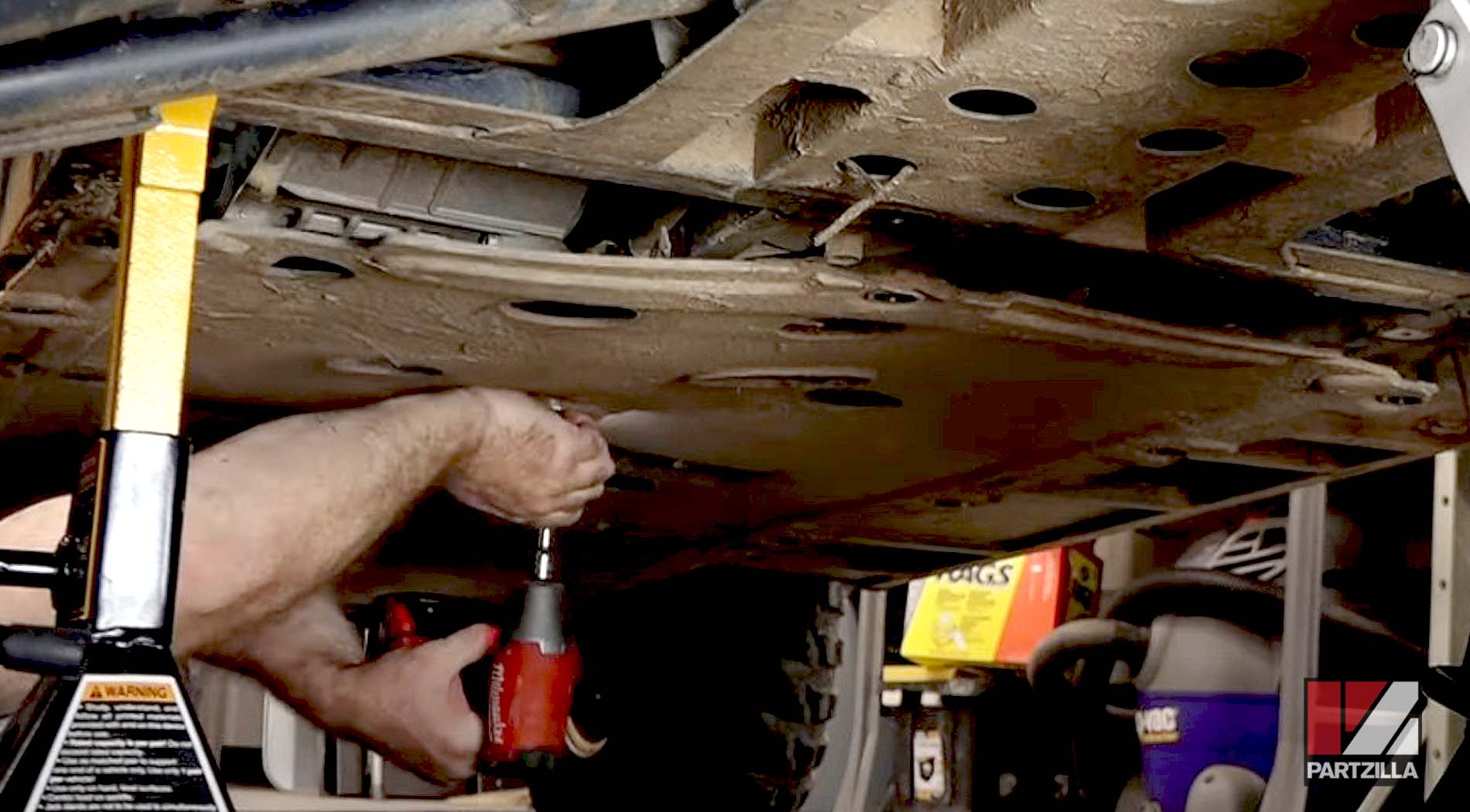
NOTE: You’ll have to remove the skid plate under the converter cover to access the two lower M8 bolts.
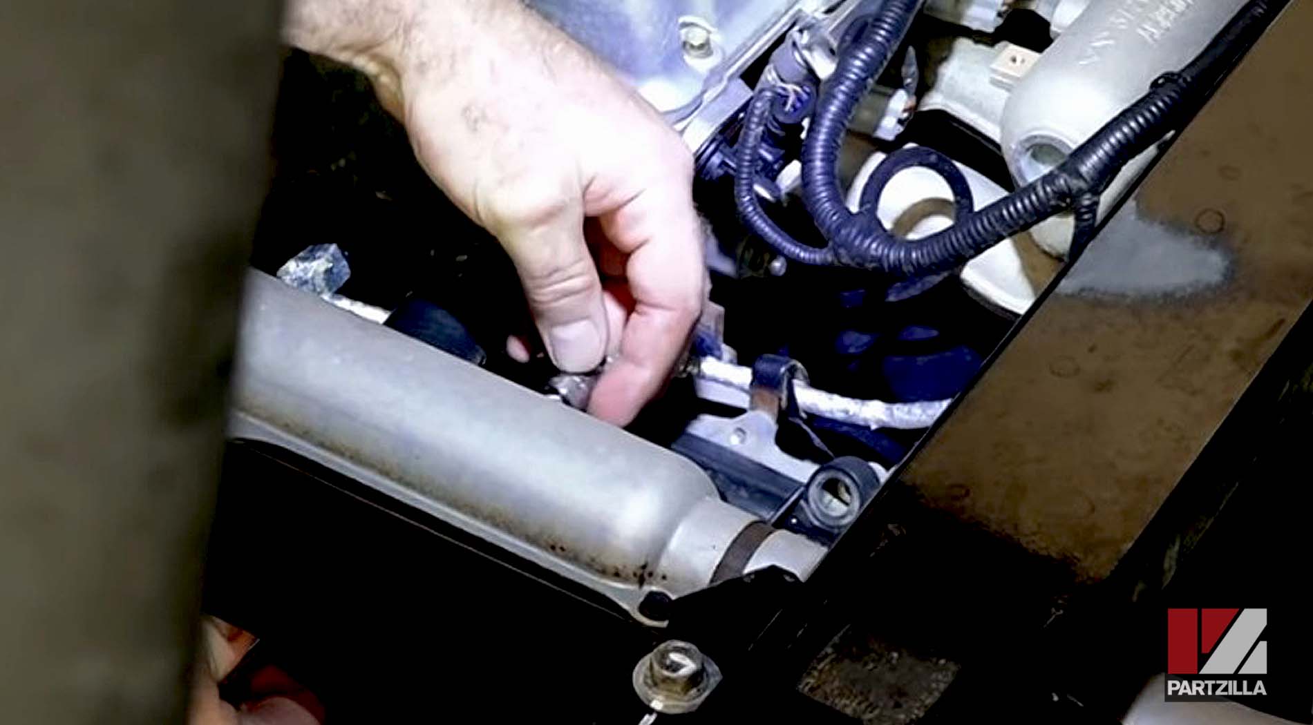
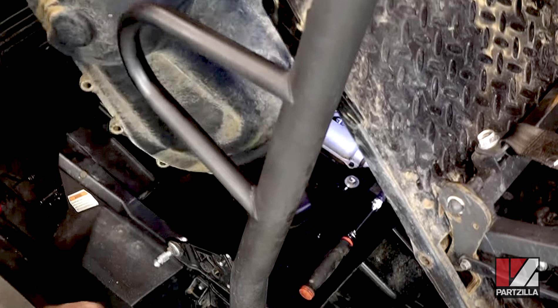
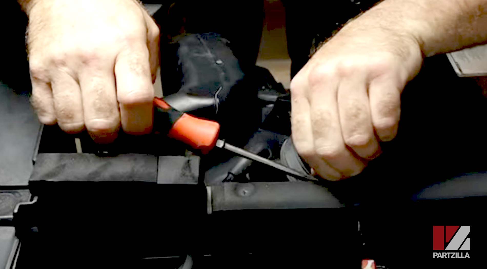
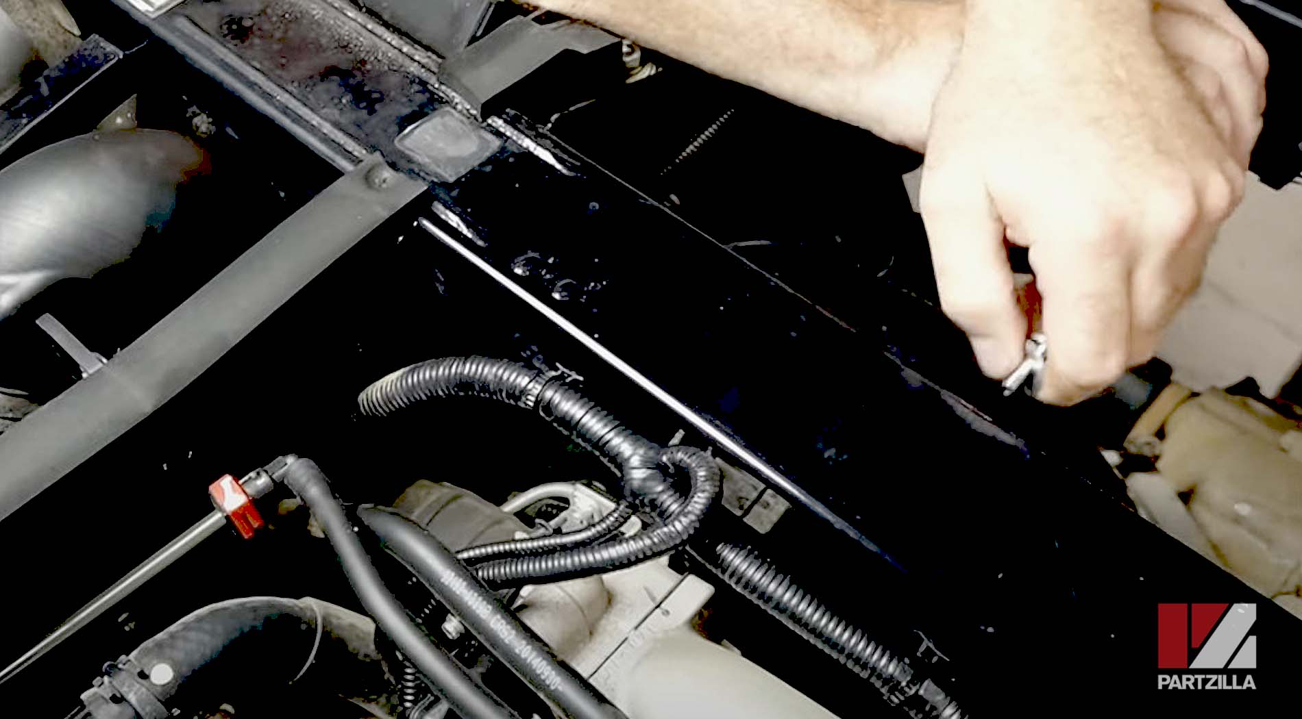
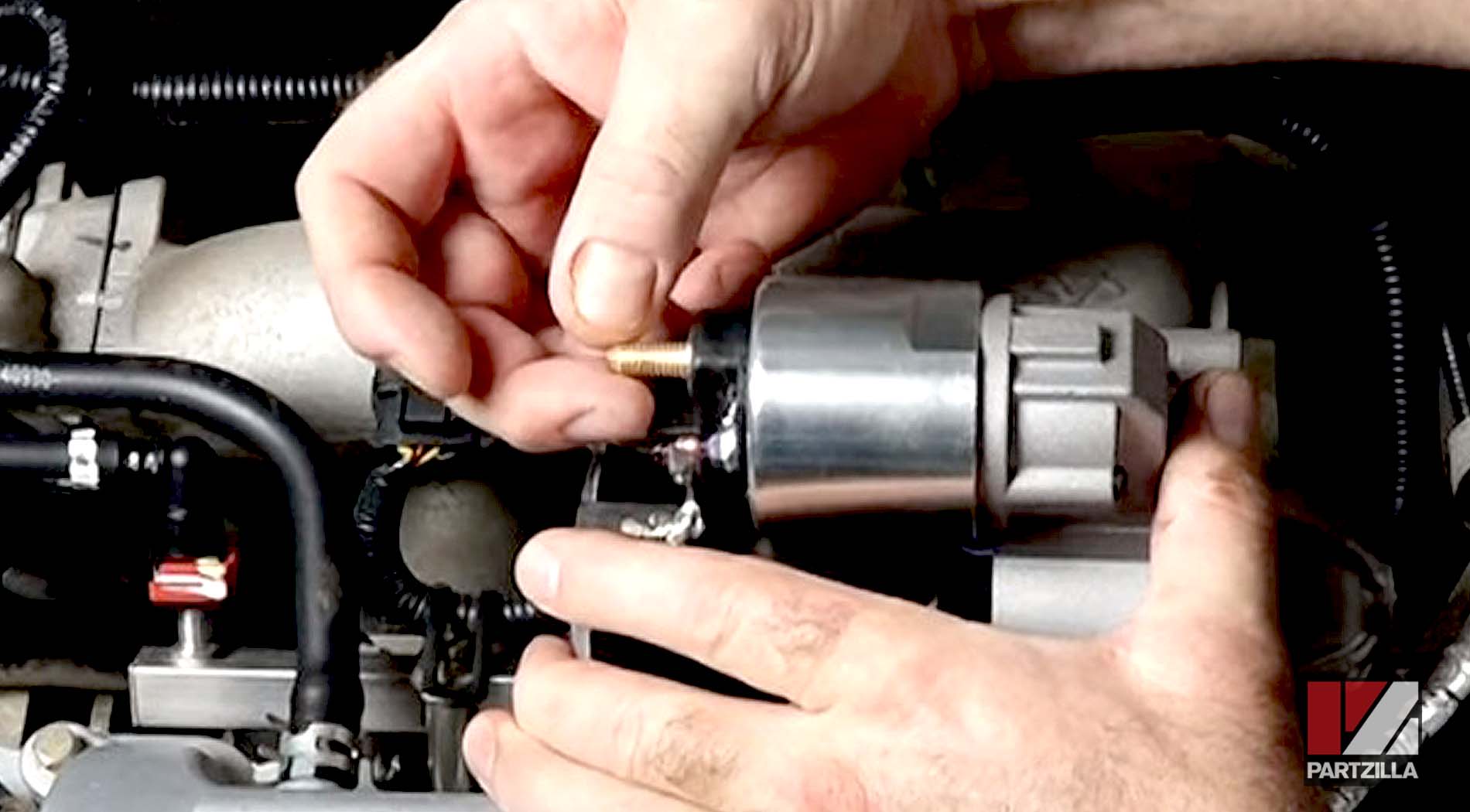
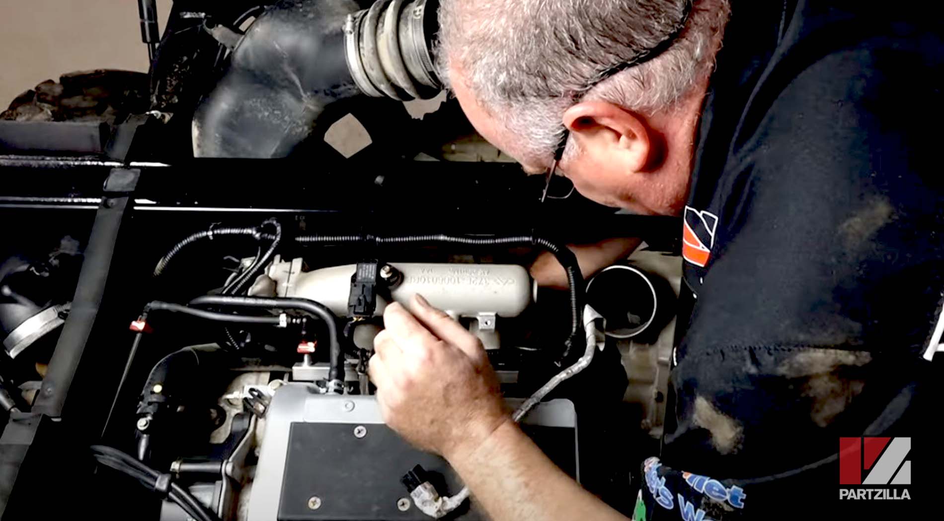
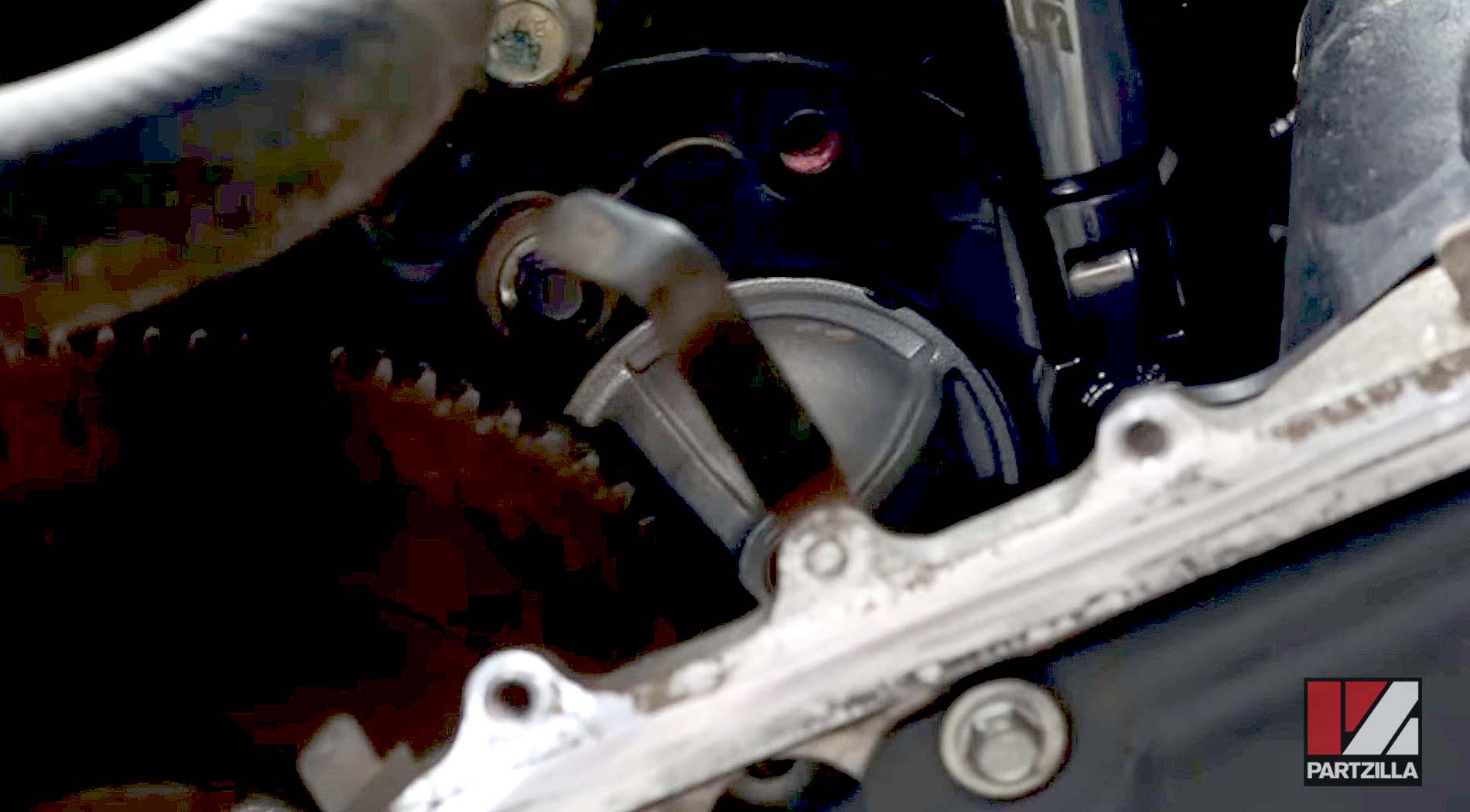
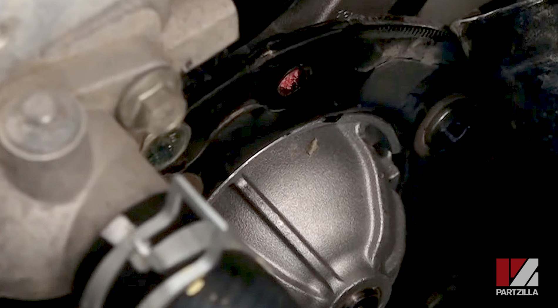
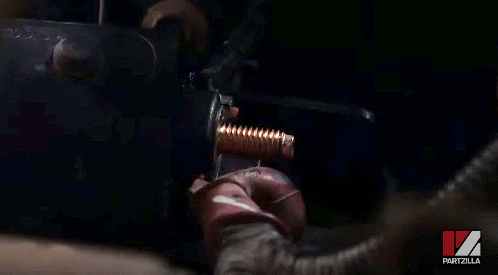
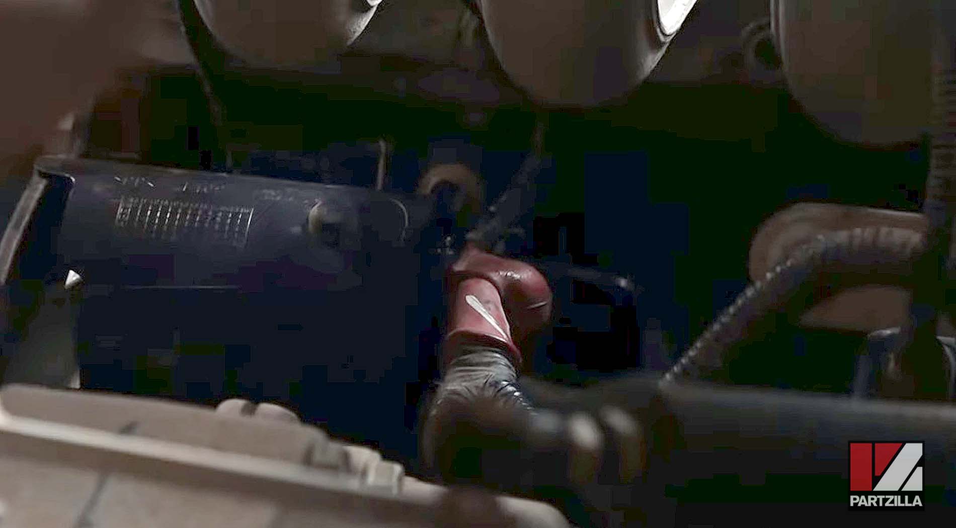
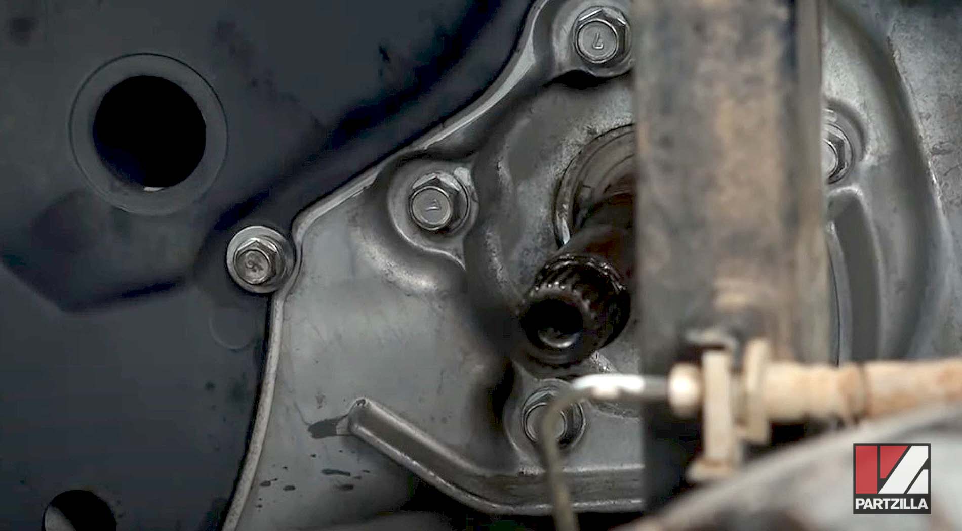
Step 12: Pull back the rubber cover from the electrical posts on the starter motor's solenoid, which is located below the air intake manifold. Remove the 8mm and 13mm retaining nuts, and disconnect the electrical cables.
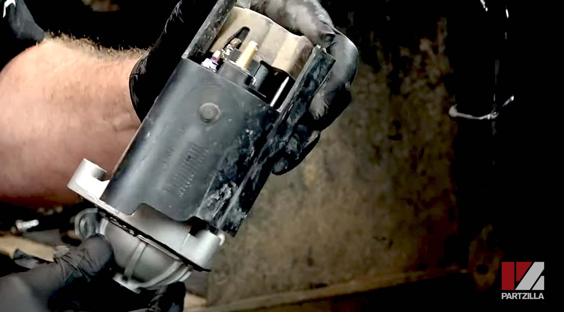
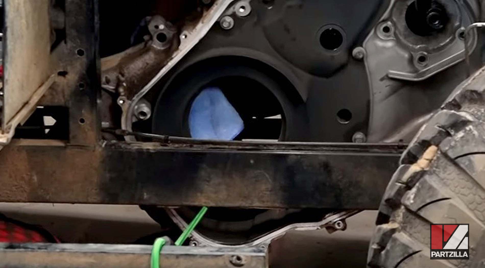
Step 13: Remove the starter motor by taking off the two 10mm bolts holding the starter motor to its mounting plate, then remove the starter motor itself.
How to Install Kawasaki Mule PRO-FXT Starter Motor
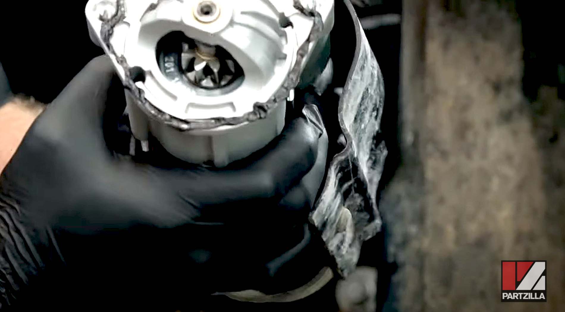
Step 1: Put a bead of high temperature bonding compound around the mating surfaces of the new starter motor.
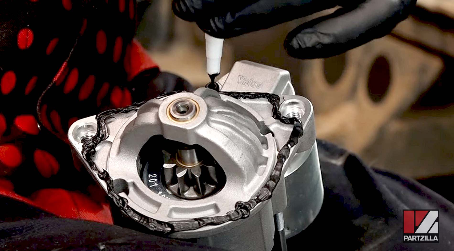
NOTE: The starter motor must be completely sealed once it is installed, otherwise water will penetrate the motor and it will corrode and fail.
NOTE: Make sure the two dowel pins are in place on the starter motor mounting plate, and that the starter motor sits on the dowels.
Step 3: Apply blue threadlocker to the two 10mm starter motor mounting bolts, and reinstall the bolts. Torque the bolts to 18 foot-pounds.
Step 4: Reinstall the 8mm and 13mm cables onto the solenoid's electrical posts, and push the rubber cover back over the terminals.
Step 5: Clean the mating surfaces of the engine and the converter cover, then apply a bead of high temperature bonding compound and reinstall the cover.
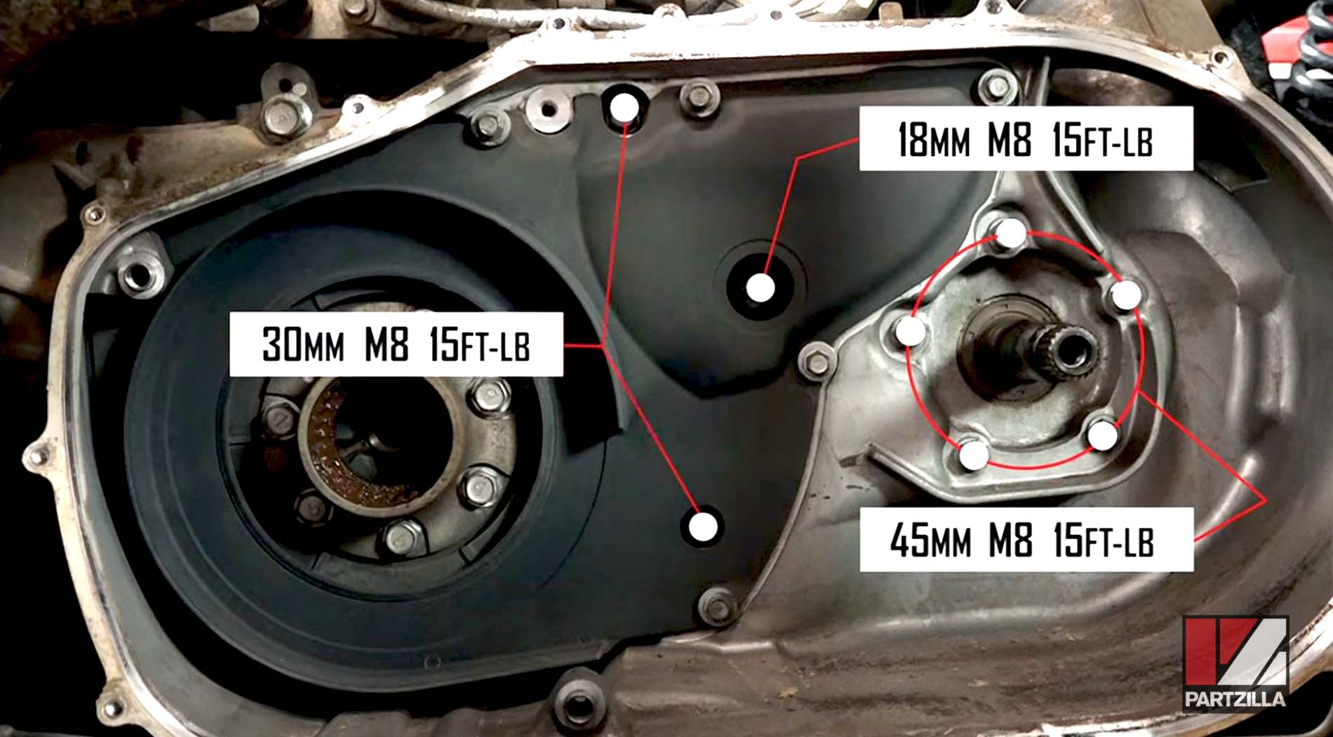
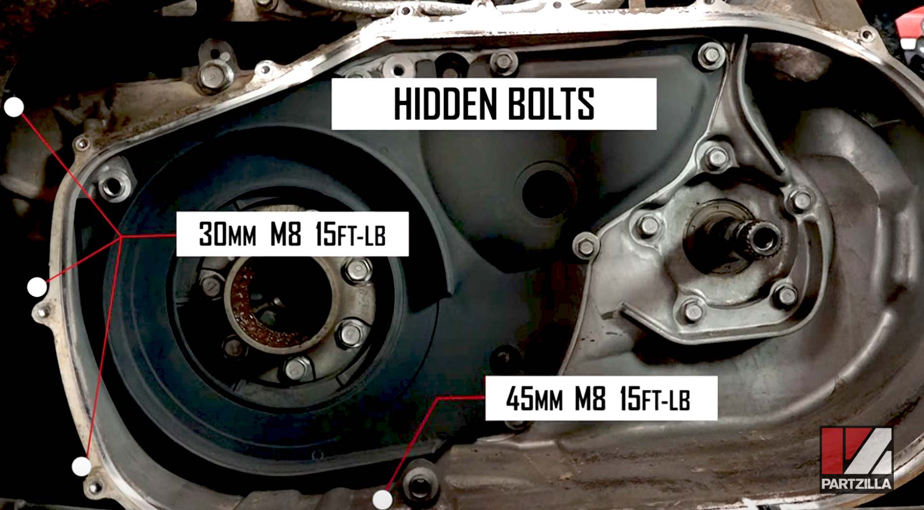
Step 6: Reinstall the M8 bolts.
NOTE: The bolts are of differing lengths, so follow the diagrams below for the correct bolt sizes and locations. Torque all the M8 bolts to 15 foot-pounds.
Step 7: Reinstall the 17mm oil channel bolt at the top of the converter cover, and torque it to 70 foot-pounds.
Step 8: Reinstall the air exhaust duct, and the air intake duct.
Step 9: Grease the engine coupling and the transmission input shaft that hold the drive and driven clutch assemblies, respectively.
Step 10: Open up the driven clutch sheaves by inserting and tightening three M8 bolts through the outer sheave. Put the drive belt over the driven clutch, making sure the belt is facing the same direction as when you removed it.
Step 11: Reinstall the driven clutch assembly onto the transmission input shaft, and reinstall the drive clutch assembly onto the engine coupling. Once the clutch assemblies and drive belt are in place, release the driven clutch sheaves by removing the three M8 bolts from the outer sheave.
Step 12: Reinstall the bearing carrier, making sure the two dowel pins are in place, and torque its three bolts to 18 foot-pounds.
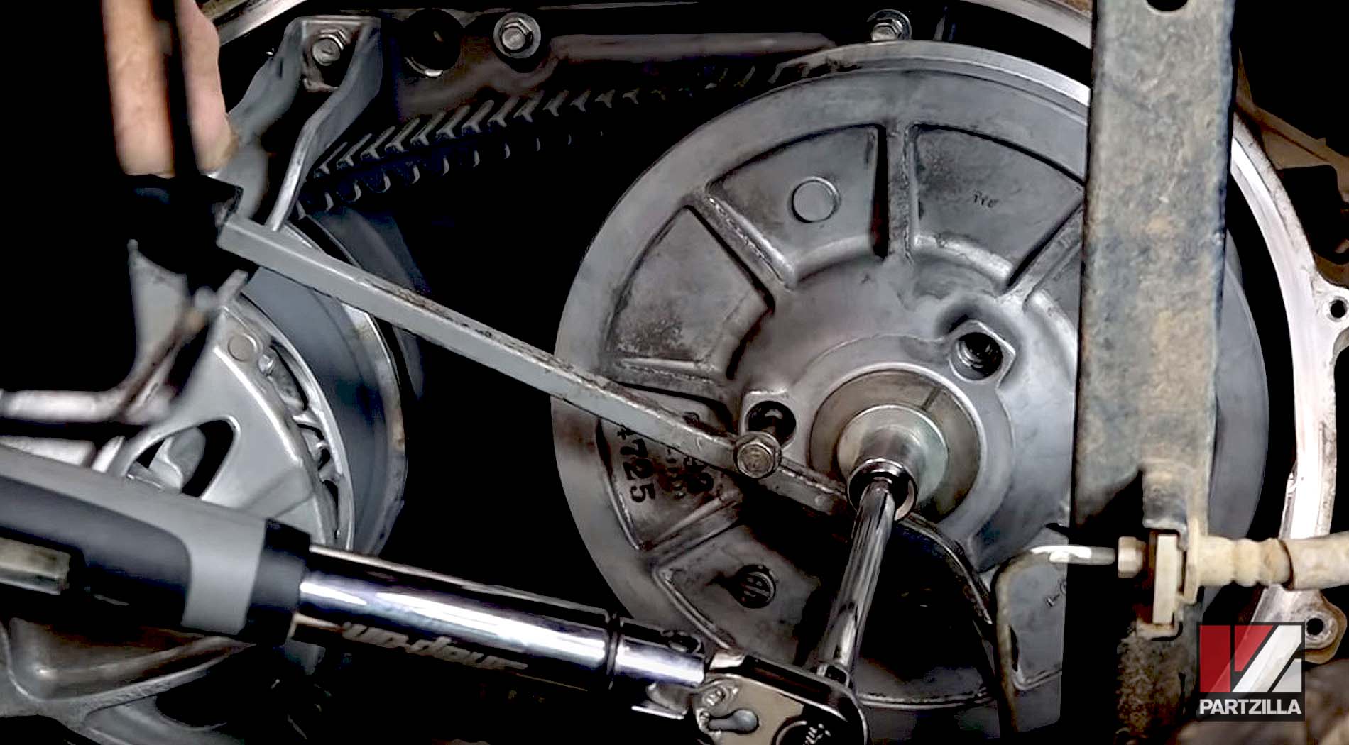
Step 13: Reinstall the driven clutch assembly center bolt and washer, and torque it to 69 foot-pounds. Prevent the driven clutch from turning while tightening the center bolt by installing a couple of M8 bolts into the outer sheave and holding them in place with a pry bar. Remove the M8 bolts once the center bolt is torqued down.
Step 14: Inspect the rubber seal around the outer converter cover, and replace it if necessary. Reinstall the outer converter cover and the fifteen 10mm bolts.
Step 15: Reinstall the inner fender in front of the left-rear wheel and the side panel.
Step 16: Reconnect the negative cable to the battery, then reinstall the battery cover and tilt the rear cargo bed back down and you're done.