How to Test Powersports Stators
The electrical system on a motorcycle, ATV or UTV consists of the battery, the regulator-rectifier and the stator. If the electrical system in your powersports vehicle is failing to charge, the problem lies with one of those three components.
Watch the video above and follow the steps below to learn how to test a motorcycle, ATV or side-by-side stator.
Tools - Powersports Vehicle Stator Testing
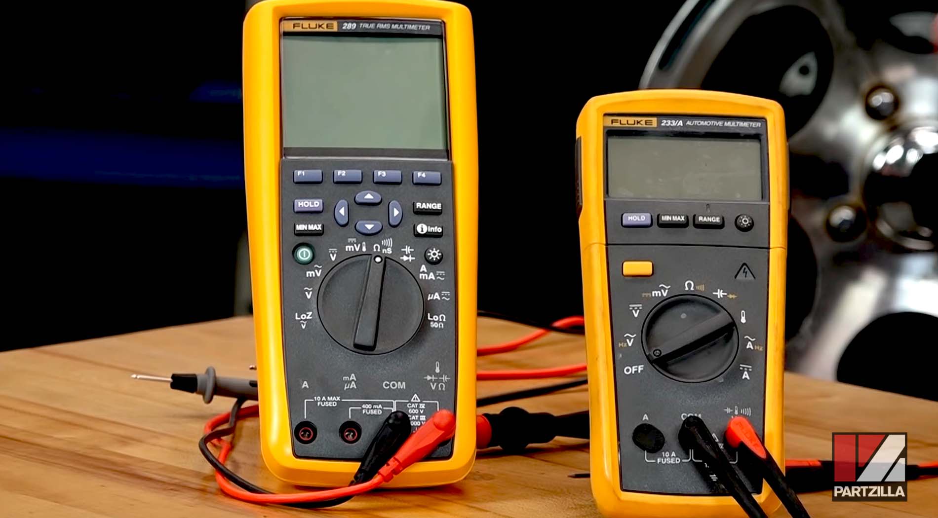
- Digital multimeter

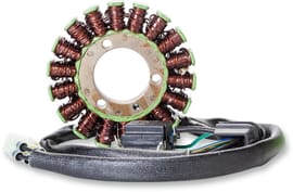
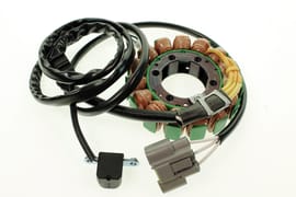
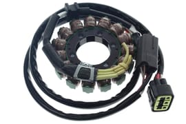
What is a Stator?
A stator is a stationary set of wire coils (the stator windings) attached to an engine, and a rotating set of magnets (the rotor or flywheel) is mounted over the stator. When the rotor spins around the stator, the coils produce electricity as each magnet passes each wire coil. The stator/rotor assembly is collectively known as an alternator.
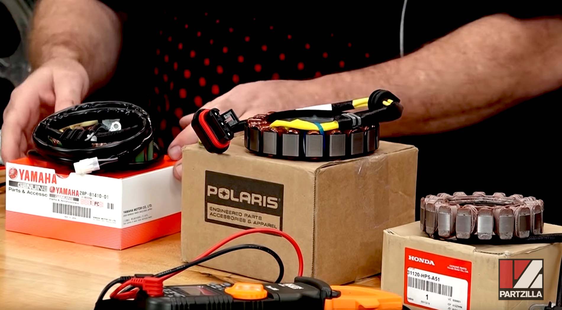
In simple terms, the stator generates the electricity that powers the battery. Aside from wear over time, not much can go wrong with the rotor. However, the stator is much more prone to failure because it's made from thin strands of wire. Units found in powersports machines are generally 3-phase stators. These consist of three separate windings wrapped around a series of points that circle the unit, with the ends of the three windings leading to an electrical connector.
Testing a Stator
A stator test is either static or dynamic. The dynamic test is performed while the stator is on the machine and the engine is running. And the static test is performed without the engine running, and the stator doesn't even need to be attached to the machine. When you have a problem with the electrical system in which the engine won't run, you'll have to do a static test.
A static stator test involves measuring from coil to coil — or phase to phase — within the stator, and also measuring from each coil/phase to ground. The exact range the stator should be within will vary from model to model, and manufacturer to manufacturer.
Static Stator Test
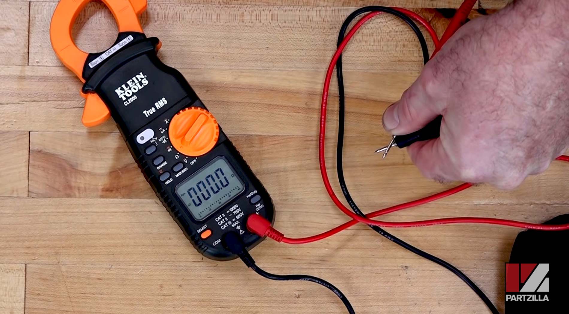
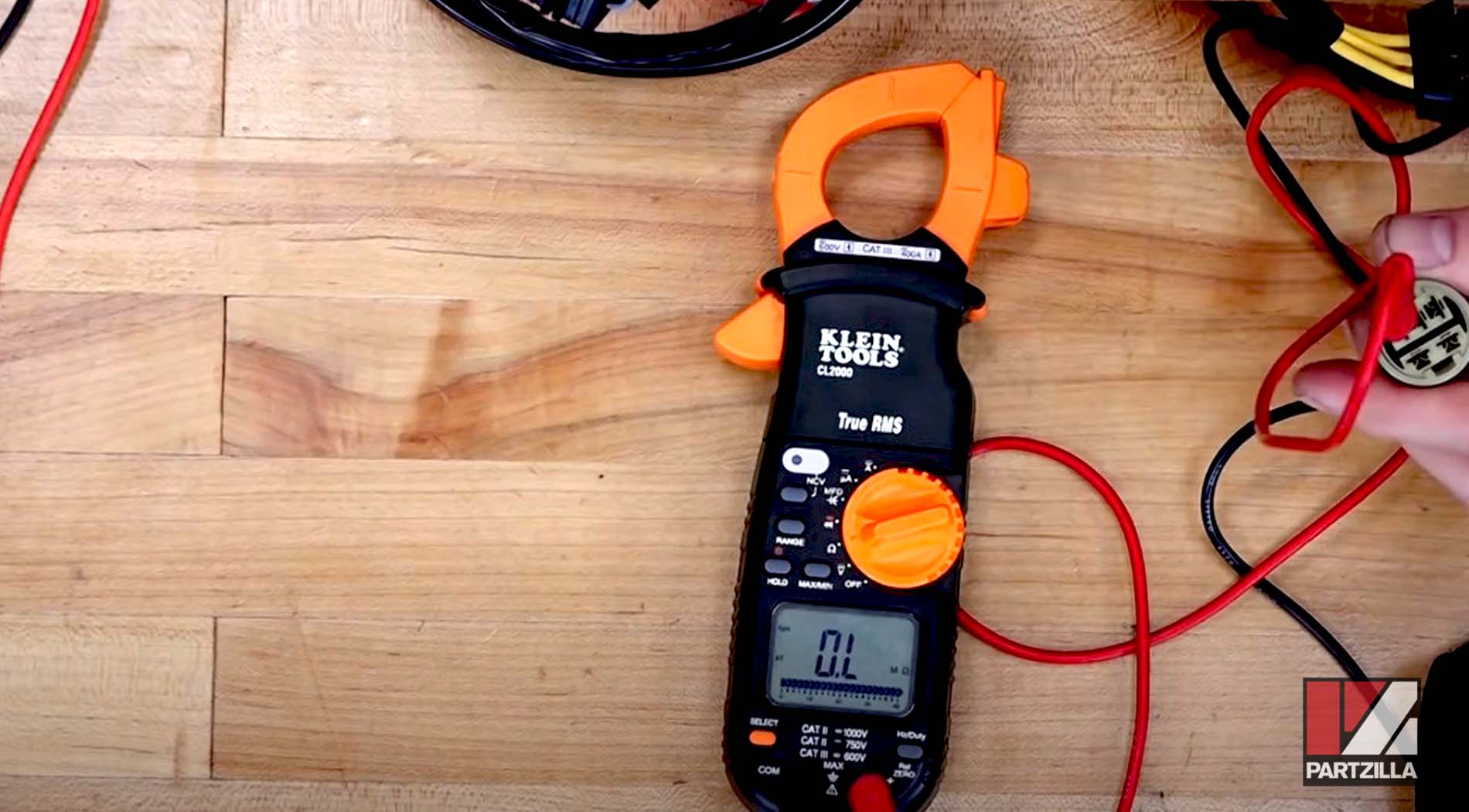
Step 1. Set the multimeter to ohms. With the multimeter's positive and negative leads apart, the display will show "OL" (open loop). This means the current circuit is open and isn't shorted or grounded. When the positive and negative leads are touched together, the display will read 0 or close to 0, because the loop is now closed.
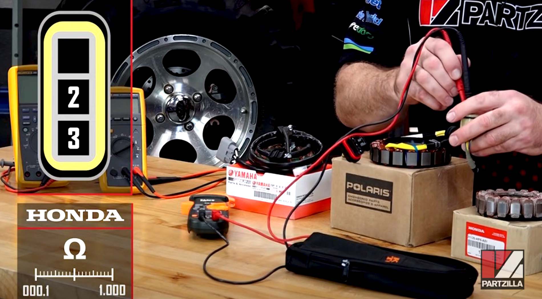
Step 2. Measure between the coils/phases by connecting the multimeter's leads to the three terminals in the stator's electrical connector. Take measurements between phases 1 and 2; 2 and 3; and 1 and 3.
Example 1. A Honda stator with a range of 0.1 ohms to 1 ohm is being measured. Such a wide range is easily measured by most multimeters.
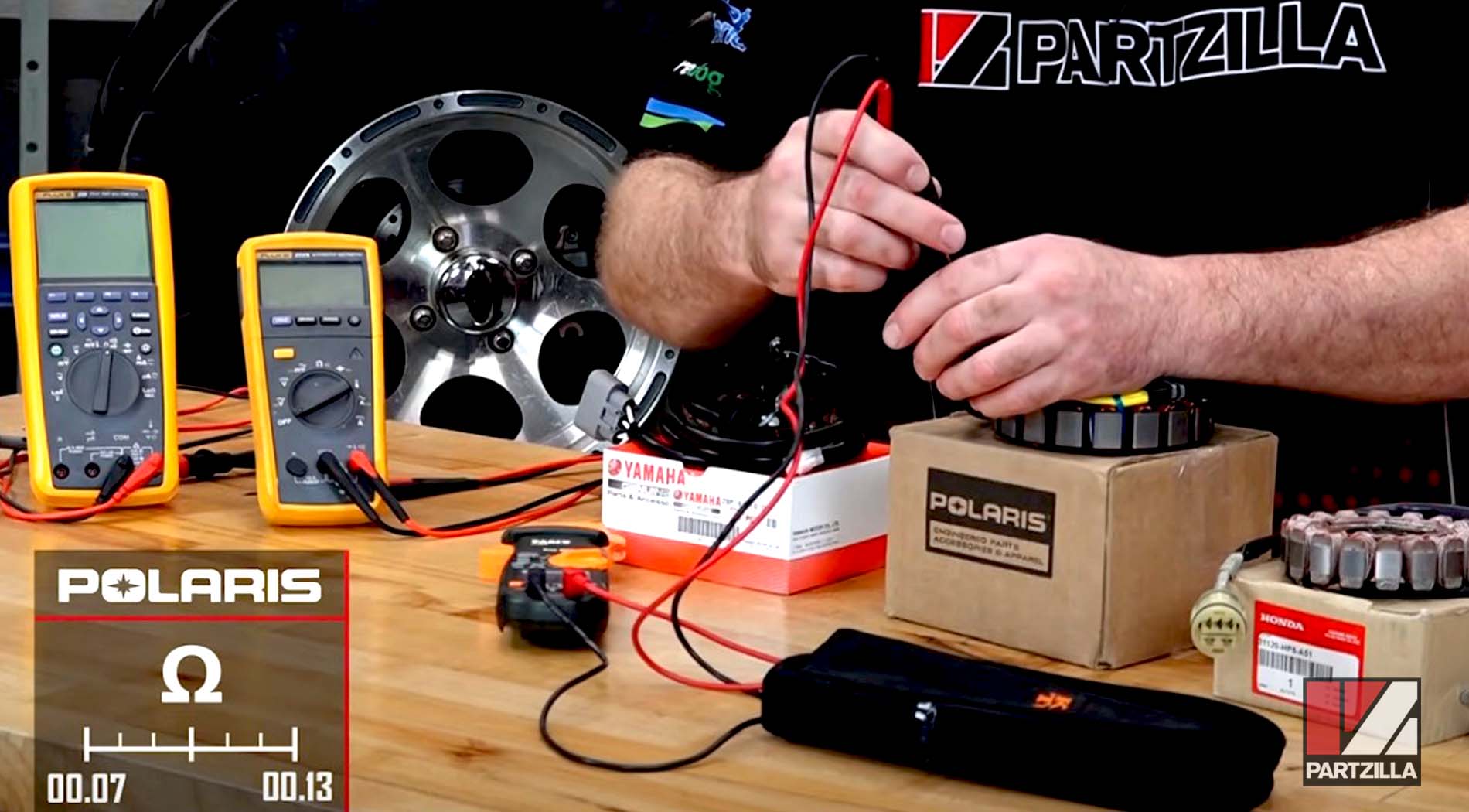
Example 2. A Polaris stator with a range of 0.07 ohms to 0.13 ohms is being measured. This smaller range requires a multimeter going to at least 1/100th of an ohm.
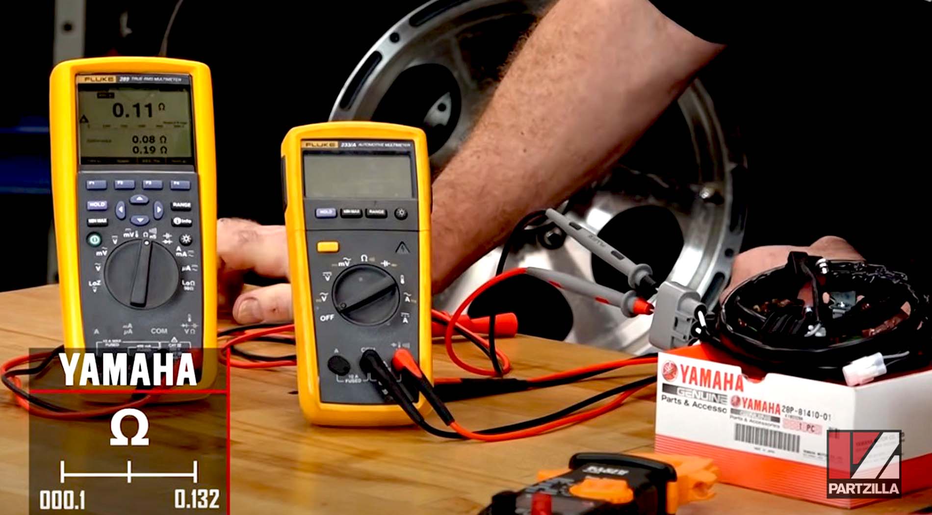
Example 3. A Yamaha stator with a range of 0.1 ohms to 0.132 ohms is being measured. This extremely small range requires special multimeters that aren't readily available at the hardware store. Therefore, it's not practical to perform a static test on such a close-ranged stator. You'll have to perform a dynamic test instead.
Step 3. Measure between each coil/phase and a ground source. Connect one of the multimeter's leads to a ground source, such as the body of the stator, and the other lead to each of the three terminals in the stator's electrical connector individually. The display should show OL, for an open loop that indicates the coil hasn't shorted or grounded.
If the stator fails any of the static tests, it will need to be replaced with an OEM stator for your vehicle's make and model.
Dynamic Stator Test
The dynamic test measures AC voltage from coil to coil — or phase to phase — within the stator. Once again, the exact range the stator should be within will vary between stator models and manufacturers.
Step 1. Set the multimeter to AC volts, then with the ignition off, measure between the coils/phases by connecting the multimeter's leads to the three terminals in the stator's electrical connector. Measure between phases 1 and 2; 2 and 3; and between 1 and 3. There should be no reading between the terminals.
Step 2. With the ignition on and the engine running, measure between the coils/phases by connecting the multimeter's leads to the three terminals in the stator's electrical connector. Measure between phases 1 and 2; 2 and 3; and 1 and 3. There should be a positive reading between the terminals.
Step 3. With the ignition on and increasing the engine's RPM, measure between the coils/phases by connecting the multimeter's leads to the three terminals in the stator's electrical connector. Measure between phases 1 and 2; 2 and 3; and 1 and 3. The reading between the terminals should increase as the RPM increases.
If the voltage readings don't change from when the ignition was off to when the engine was running, the stator is faulty and will need to be replaced. Watch the video above to see the full process of how to do a dynamic stator test.