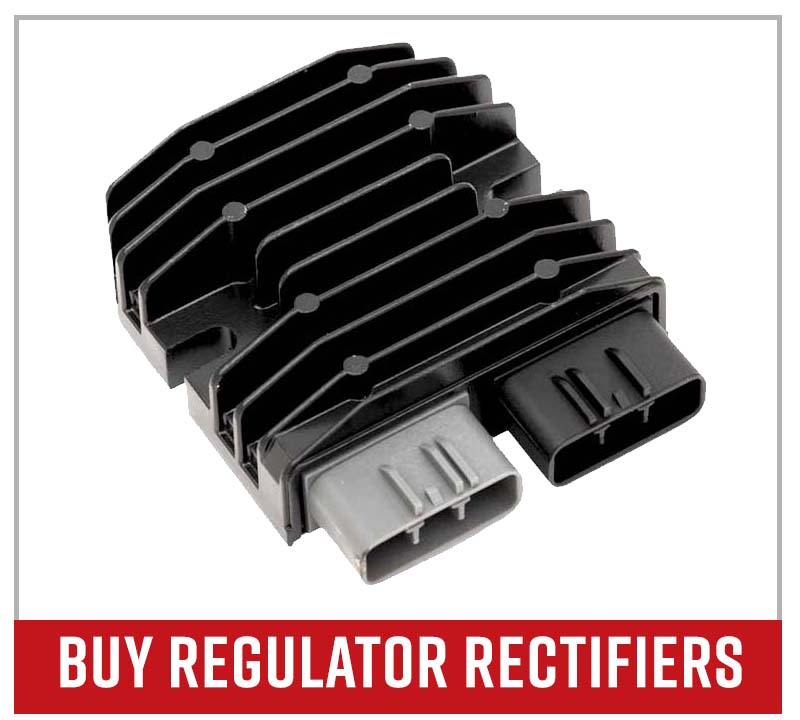
How to Test a Regulator Rectifier
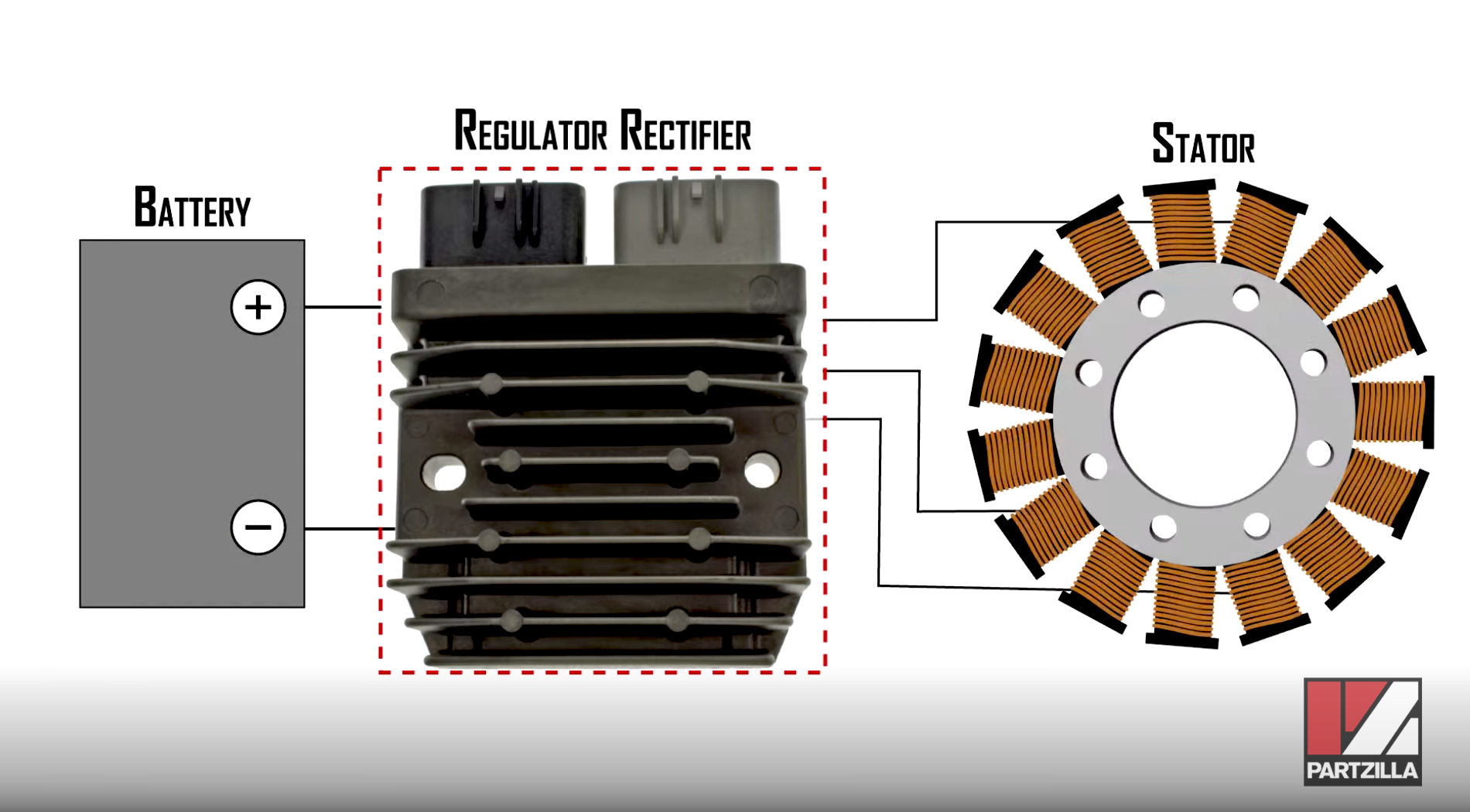
The electrical system on a motorcycle, ATV or side-by-side is made up of three components: the battery, the stator and the regulator rectifier.
If the electrical system on your vehicle isn't charging, the problem is likely one of those three components. The only way to be sure which component in the electrical system is at fault is to test all three. Watch the video above or read on below to see how to test a regulator rectifier.
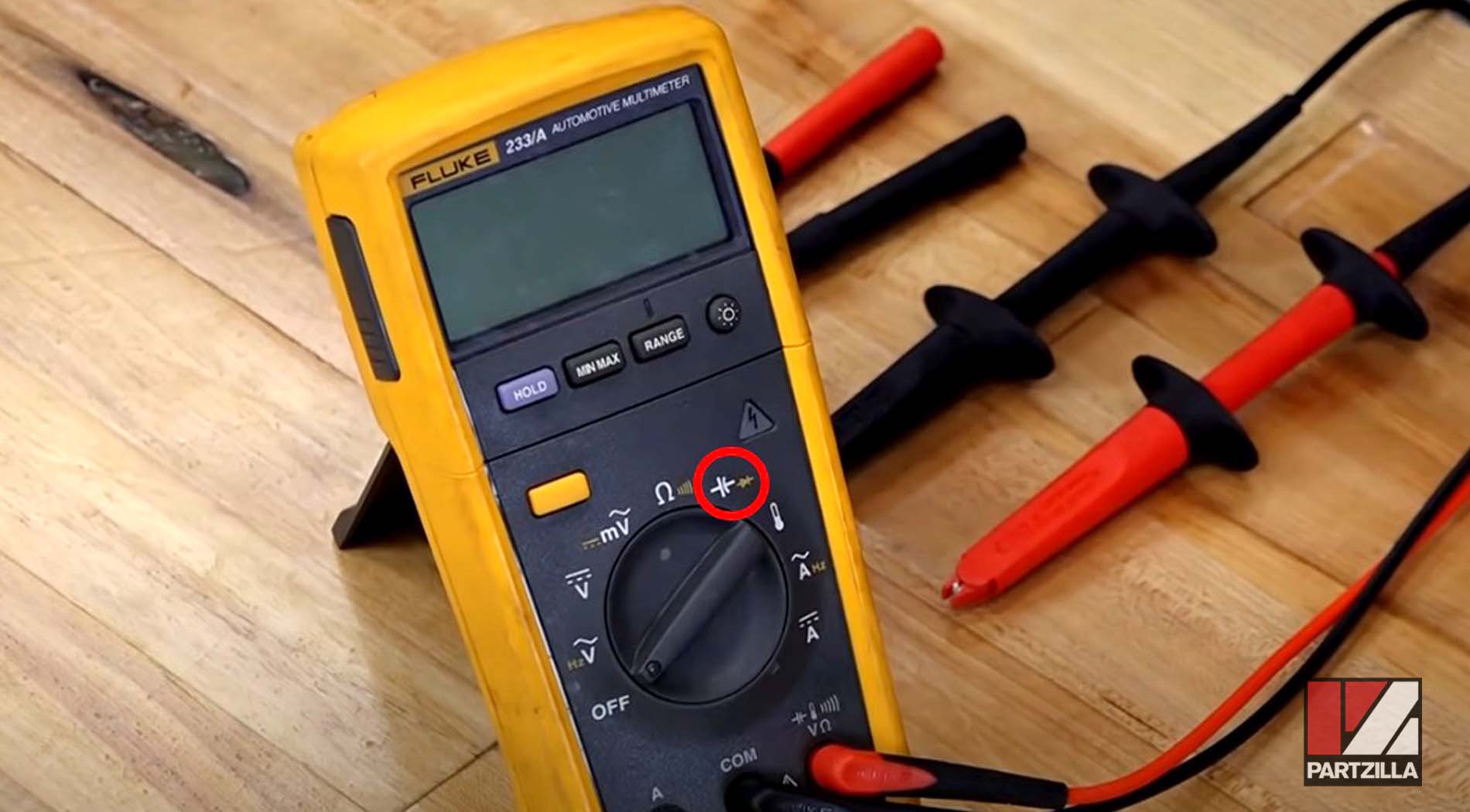
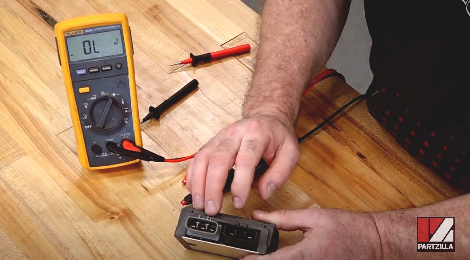
To test a regulator rectifier, you'll need a digital multimeter with diode testing capabilities. If you don't already own a multimeter, now is a good time to get one.

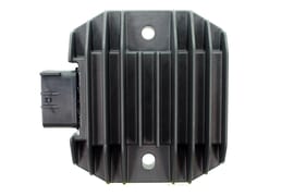
What is a Regulator Rectifier?
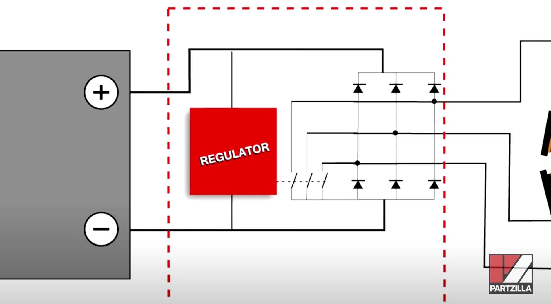
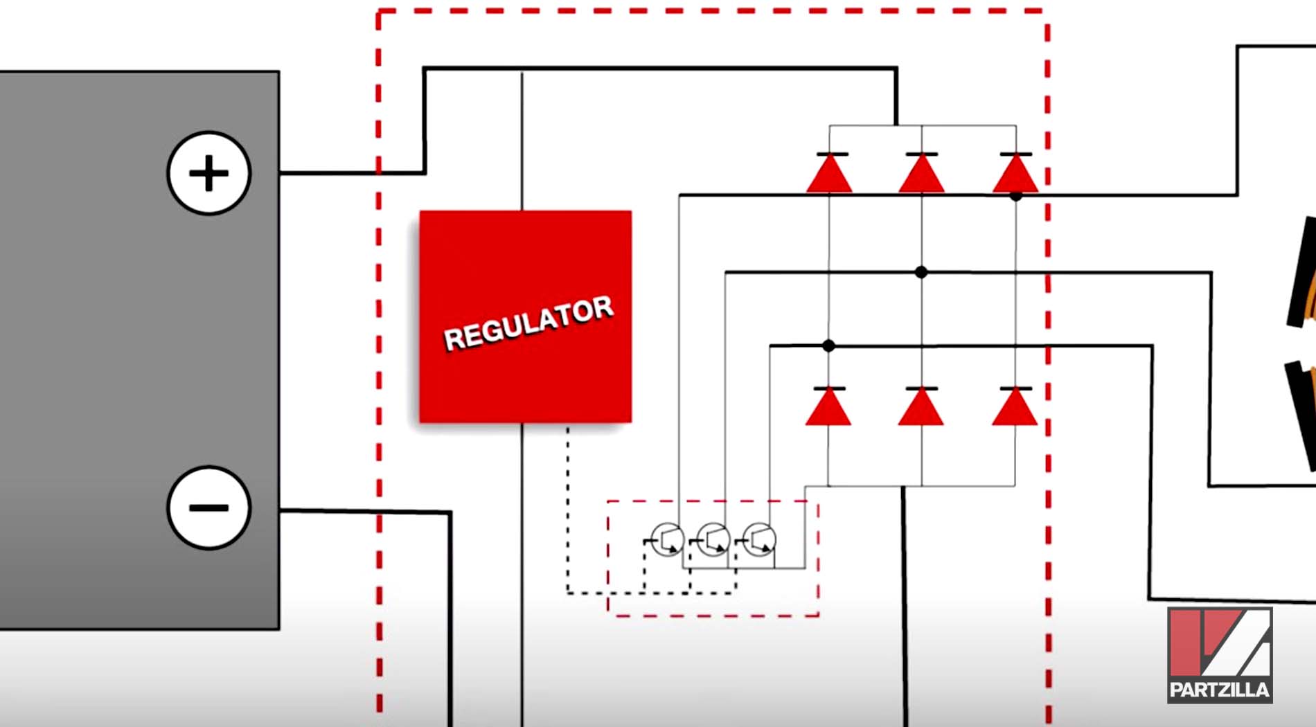
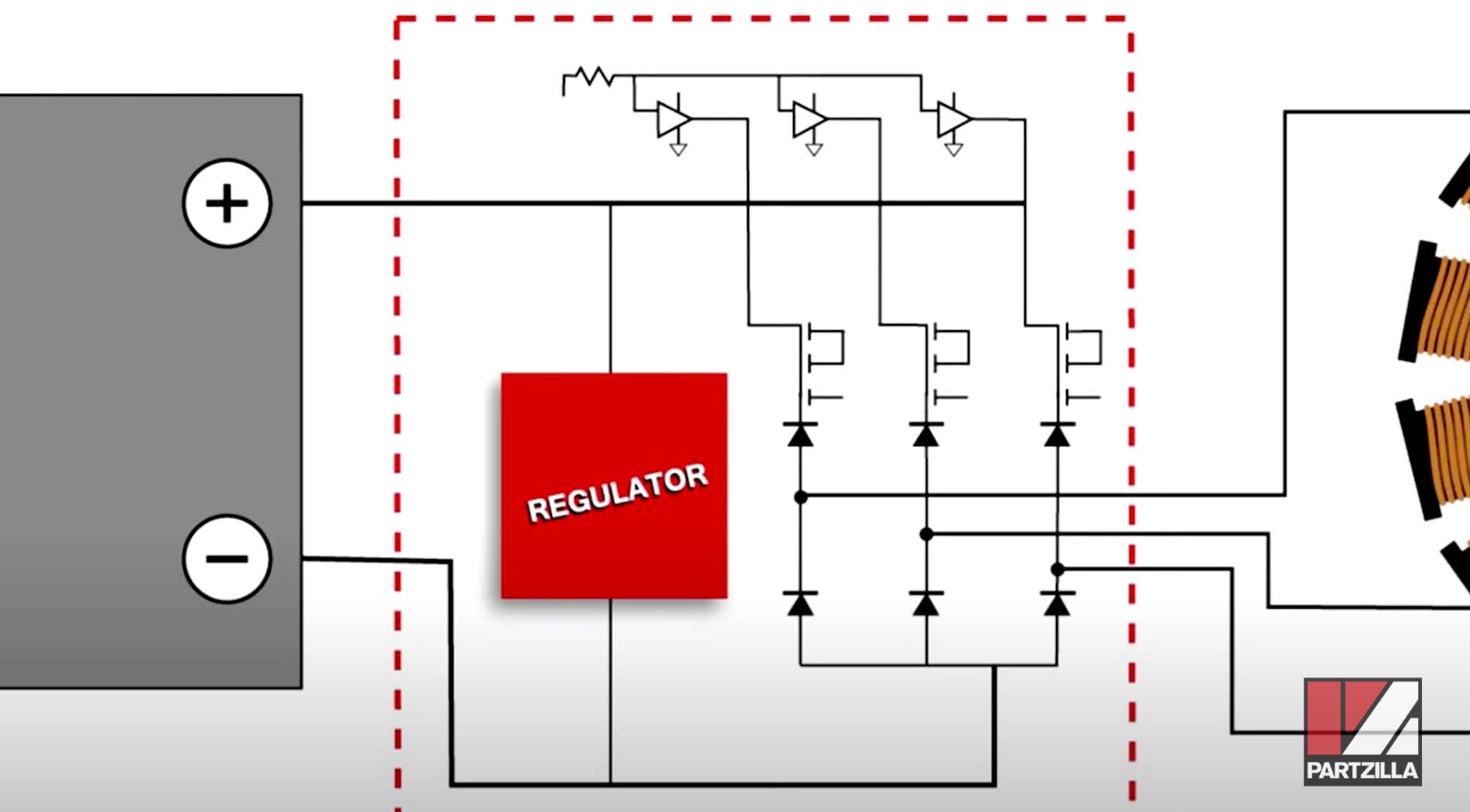
A regulator rectifier is an electronic unit that takes the AC electrical current generated by the stator, converts that current into DC electrical current, and sends the DC current to the battery. The rectifier portion of the regulator rectifier unit is responsible for converting the current from AC to DC, while the regulator portion is responsible for controlling the amount of current sent to the battery so that it doesn't damage it.
A regulator rectifier contains a set of diodes. A diode allows an electrical current to flow through it in one direction, while blocking the electrical current from flowing through it in the other direction. The flow of electrical current through a diode is known as bias, with the allowed direction of current flow called forward bias, and the blocked direction of current flow called reverse bias.
Testing a Regulator Rectifier
To determine that a regulator rectifier is working properly, it's necessary to test each of its diodes to see whether they are forward biasing (allowing current flow) and reverse biasing (preventing current flow) correctly. Regulator rectifier units vary from model to model, and manufacturer to manufacturer. Some regulator rectifiers are easier to test than others, and some can't be tested at all.
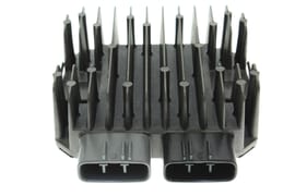
There are two electrical connectors on a regulator rectifier. These are usually a gray three-terminal connector that receives current in from the stator; and a black two-terminal connector that sends current out to the battery. The inner terminal on the black two-terminal connector is the positive terminal, and the outer terminal is the negative terminal. Some regulator rectifiers have a black three-terminal connector, with the center terminal being a ground.
NOTE: When testing a regulator rectifier, set your multimeter to the diode setting.
Regulator Rectifier Test #1: Forward Bias of Positive Circuit Diodes
Put the multimeter's negative lead on the positive terminal of the black two-terminal connector. Next, put the multimeter's positive lead on all three terminals of the gray three-terminal connector individually.
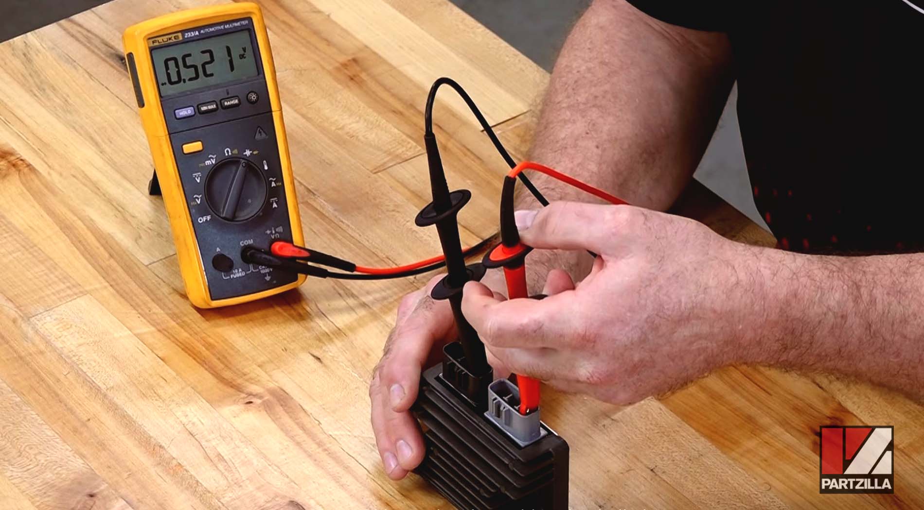
The multimeter should give a positive reading in volts, which indicates that each diode is allowing electrical current to travel through (forward bias), and is therefore functioning correctly.
Regulator Rectifier Test #2: Reverse Bias of Positive Circuit Diodes
Put the multimeter's positive lead on the positive terminal of the black two-terminal connector. Next, put the multimeter's negative lead on all three terminals of the gray three-terminal connector individually.
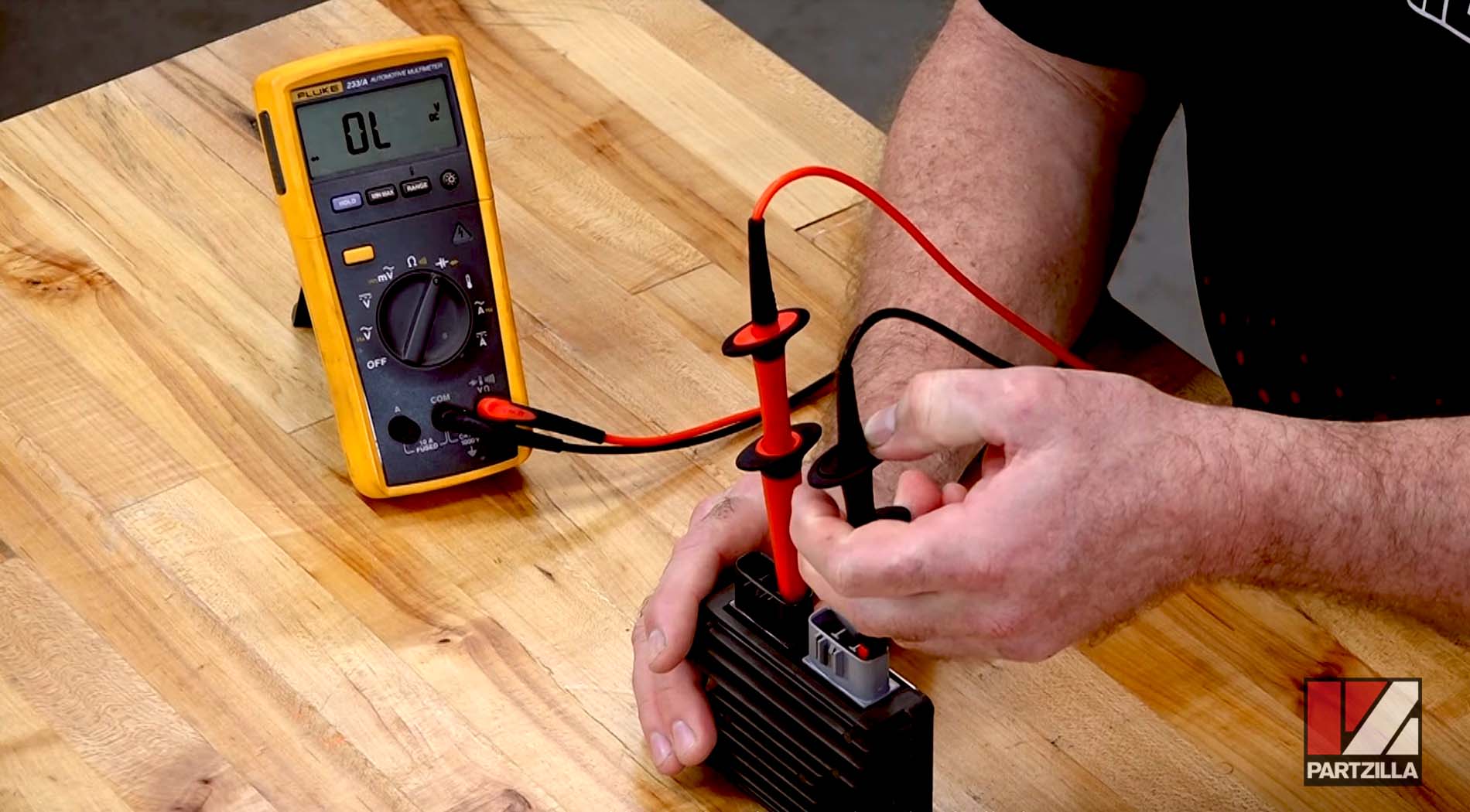
The multimeter should give a reading of "OL", which indicates that each circuit is open (OL stands for open loop) and the diode is preventing electrical current from travelling back through (reverse bias), and is therefore functioning correctly.
Regulator Rectifier Test #3: Forward Bias of Negative Circuit Diodes
Put the multimeter's positive lead on the negative terminal of the black two-terminal connector. Next, put the multimeter's negative lead on all three terminals of the gray three-terminal connector individually.
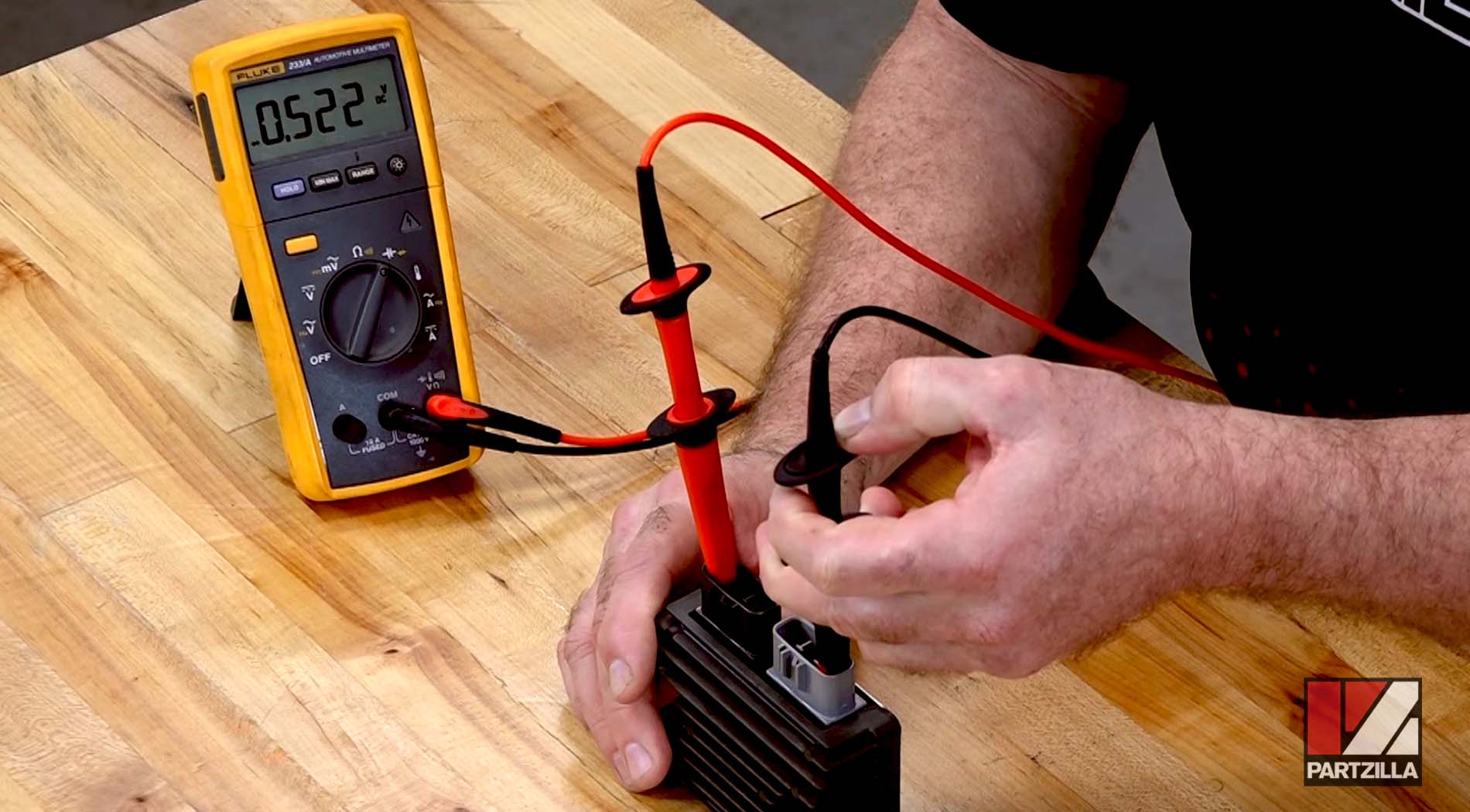
The multimeter should give a positive reading in volts, which indicates that each diode is allowing electrical current to travel through. If any of the forward bias test readings fail to show forward bias, or if any of the reverse bias test readings show a voltage, the diode has failed and the regulator rectifier unit must be replaced.
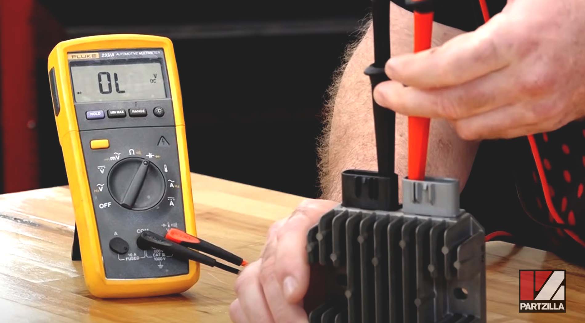
Regulator Rectifier Test #4: Reverse Bias of Negative Circuit Diodes
Put the multimeter's negative lead on the negative terminal of the black two-terminal connector. Next, put the multimeter's positive lead on all three terminals of the gray three-terminal connector individually.
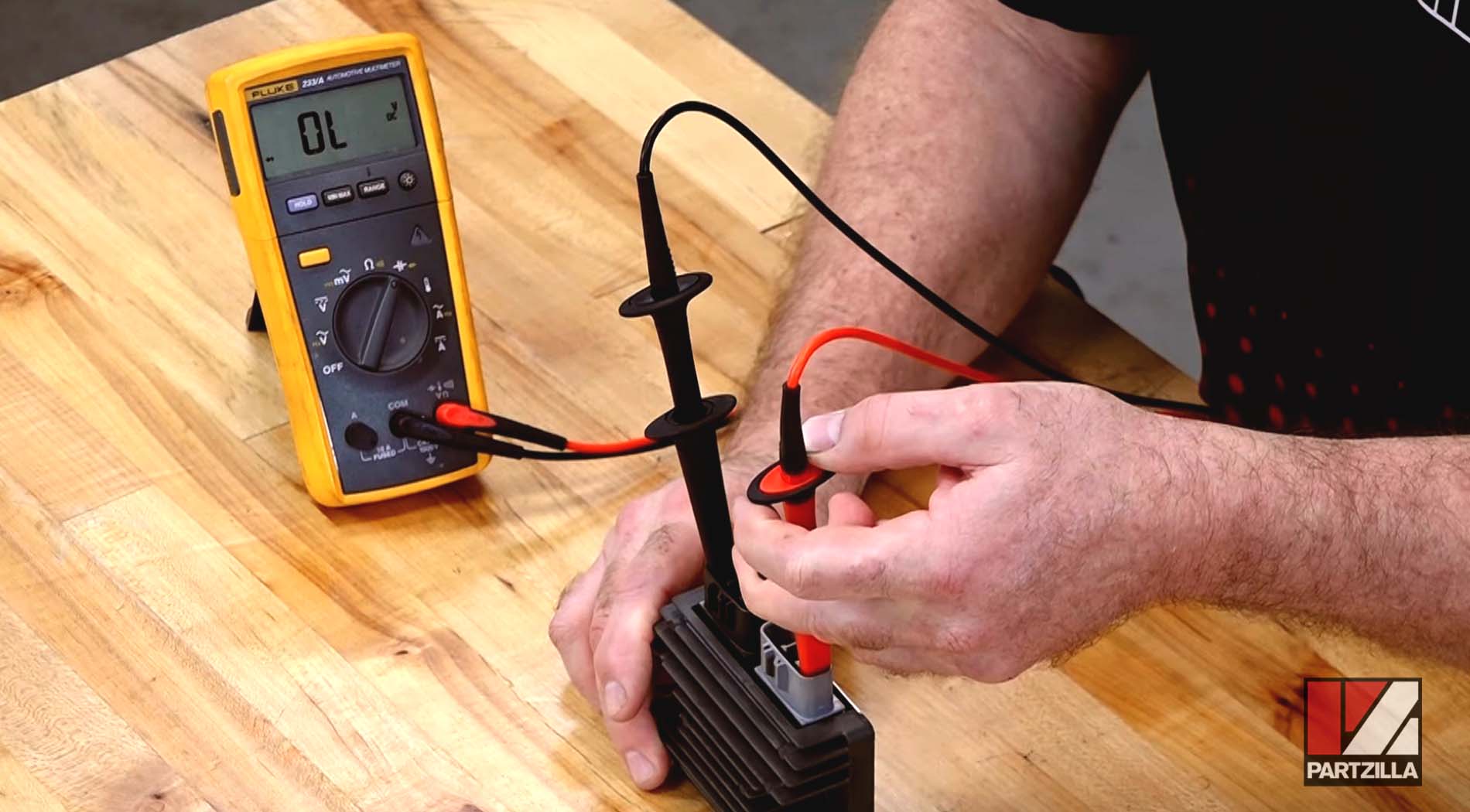
The multimeter should give a reading of "OL", which indicates that each circuit is open, and the diode is preventing electrical current from travelling back through.
Testing Regulator Rectifiers by Manufacturer
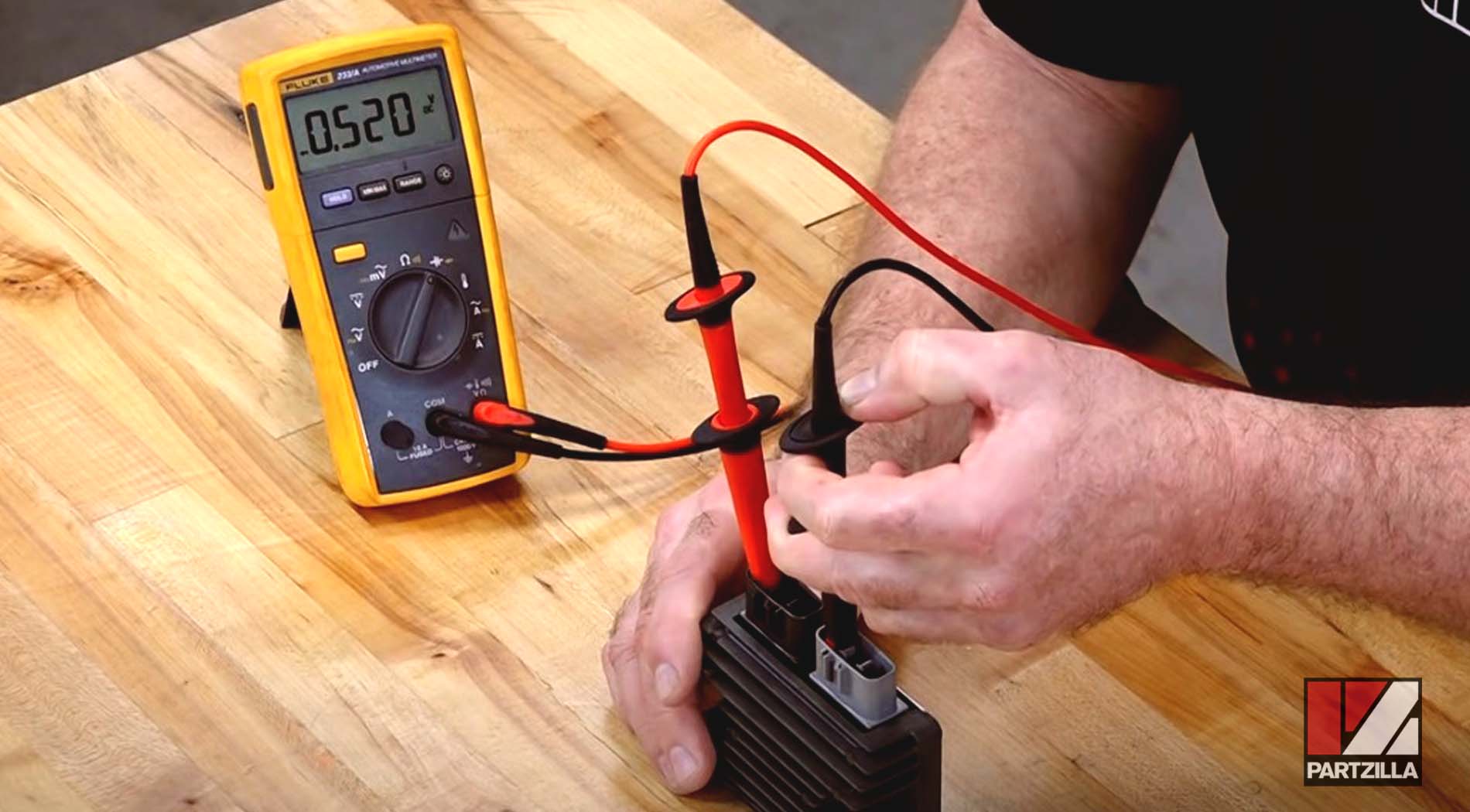
Honda Regulator Rectifier Test
The forward bias measurement for the positive terminal diodes and the negative terminal diodes in the Honda regulator rectifier should be about 0.48 volts to 0.52 volts.
Watch the clip below to see the Honda regulator rectifier test in action.
Yamaha Regulator Rectifier Test
The forward bias measurement for the negative terminal diodes in the Yamaha regulator rectifier should be about 0.48 volts to 0.52 volts, and the positive terminal diodes should be about 0.12 volts.
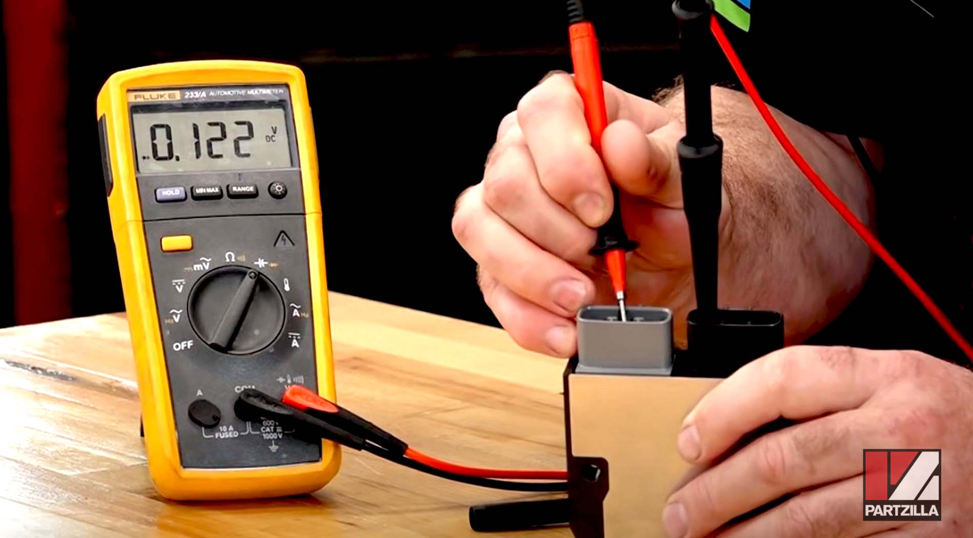
The reason for the change in readings between the positive and negative circuit diodes is that there's additional circuitry within the Yamaha regulator rectifier that affects the readings.
Watch the clip below to see the Yamaha regulator rectifier test in action
Polaris Regulator Rectifier Test
The forward bias measurement for the negative terminal diodes in the Polaris regulator rectifier should be about 0.48 volts to 0.52 volts. However, the reading from the negative terminal diodes will show OL.
The reason for the change in readings between the diodes is the additional circuitry within the regulator rectifier affecting the readings.
Watch the clip below to see the Polaris regulator rectifier test in action.
Although you can test some or all of the diodes on most regulator rectifiers, on others the circuitry on the regulator side of the unit prevent you from testing both the positive and negative sides of the rectifier's circuit. If your vehicle's electrical system isn't charging properly, and the regulator rectifier is one that can't be completely tested with a multimeter, use a process of elimination to determine which of the three main components is at fault.
Watch the video below for more on how to test an ATV stator, rectifier and battery.
Test that the stator is generating power and test the wiring for shorts. If all those tests check out, then the regulator rectifier has to be the problem.
Watch the video below for more on how to test a stator on a motorcycle, ATV or UTV.